How to slope from the Boundary? Or stop the slope before it reaches the ground or another platform? With the upcoming feature of a wall line in MiTS, these scenarios can be easily achieved.
What is the wall line? #
Wall line can be viewed as a special case of a platform – a special kind of platform that has only lines and no area. Users can also assign the wall line to have a slope or not. It also acts as a boundary, touching the wall line will stop the slope from the nearby platforms from generating.
How to use wall line feature? #
- Open Earthwork module
- Input > Wall Lines > Edit
- Click once on the input screen till the ‘+‘ symbol appears
- Start designing your wall line:
- Slope stopper
- Slope generation along wall line
- Retaining wall at toe slope
- Slope from Boundary
Wall line as slope stopper #
- Create a wall line beside the platform according to your project
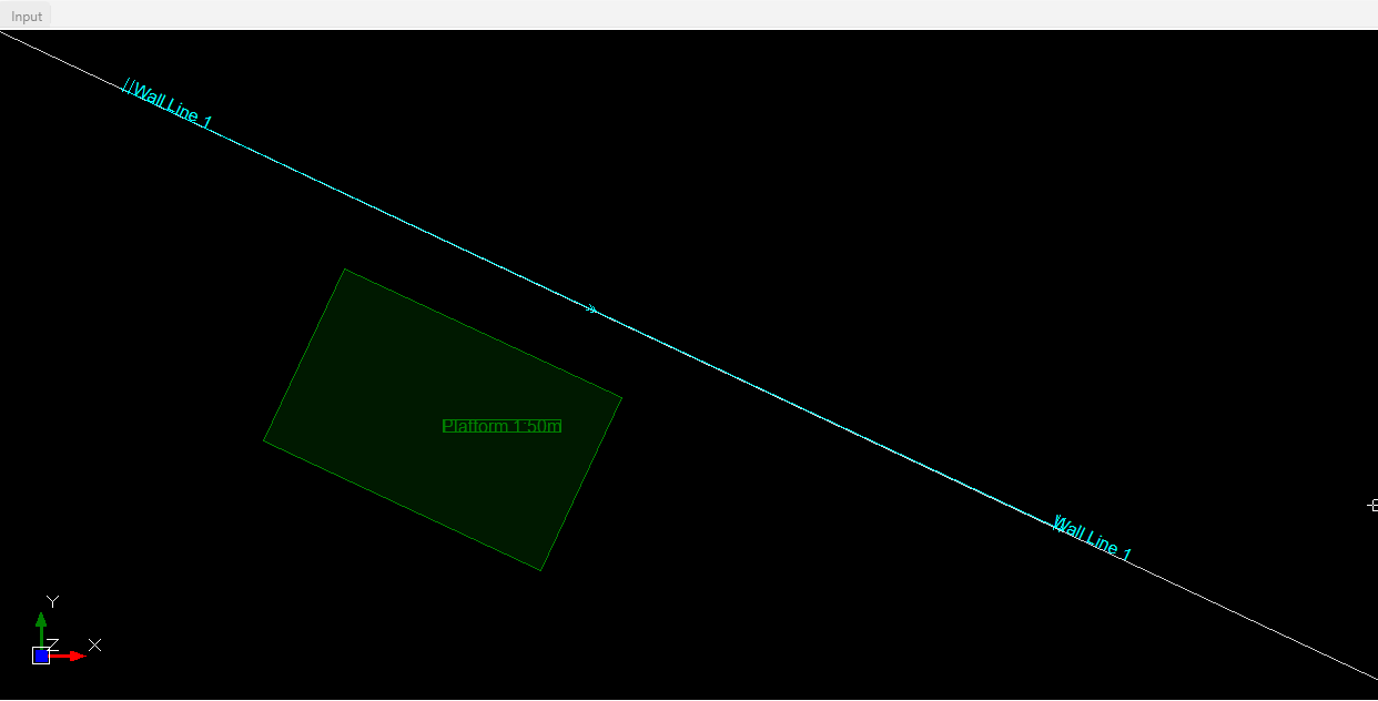
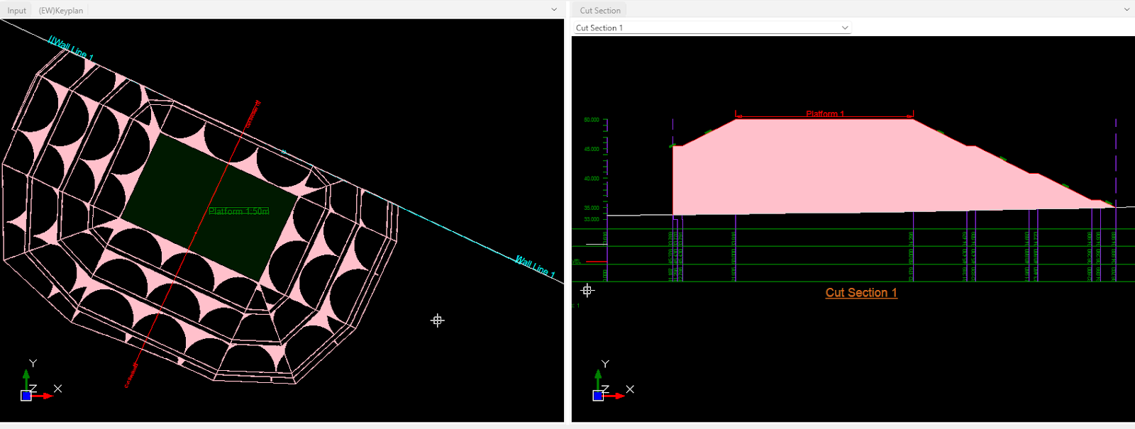
- Generate slope. Create a cut line to view its cut section
Generate slope from wall line #
Friendly note: This is an example scenario
If your project’s boundary has a slope, but there is no platform to create a slope, and the boundary feature also can’t generate a slope, you do not need to fret since you can use this wall line to create a slope.
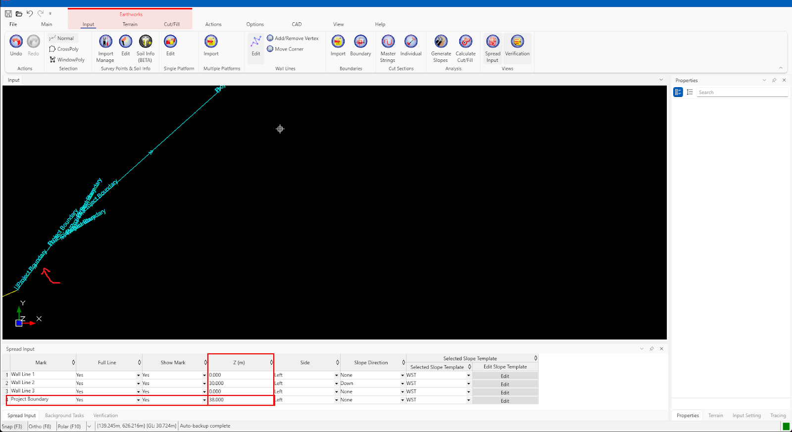
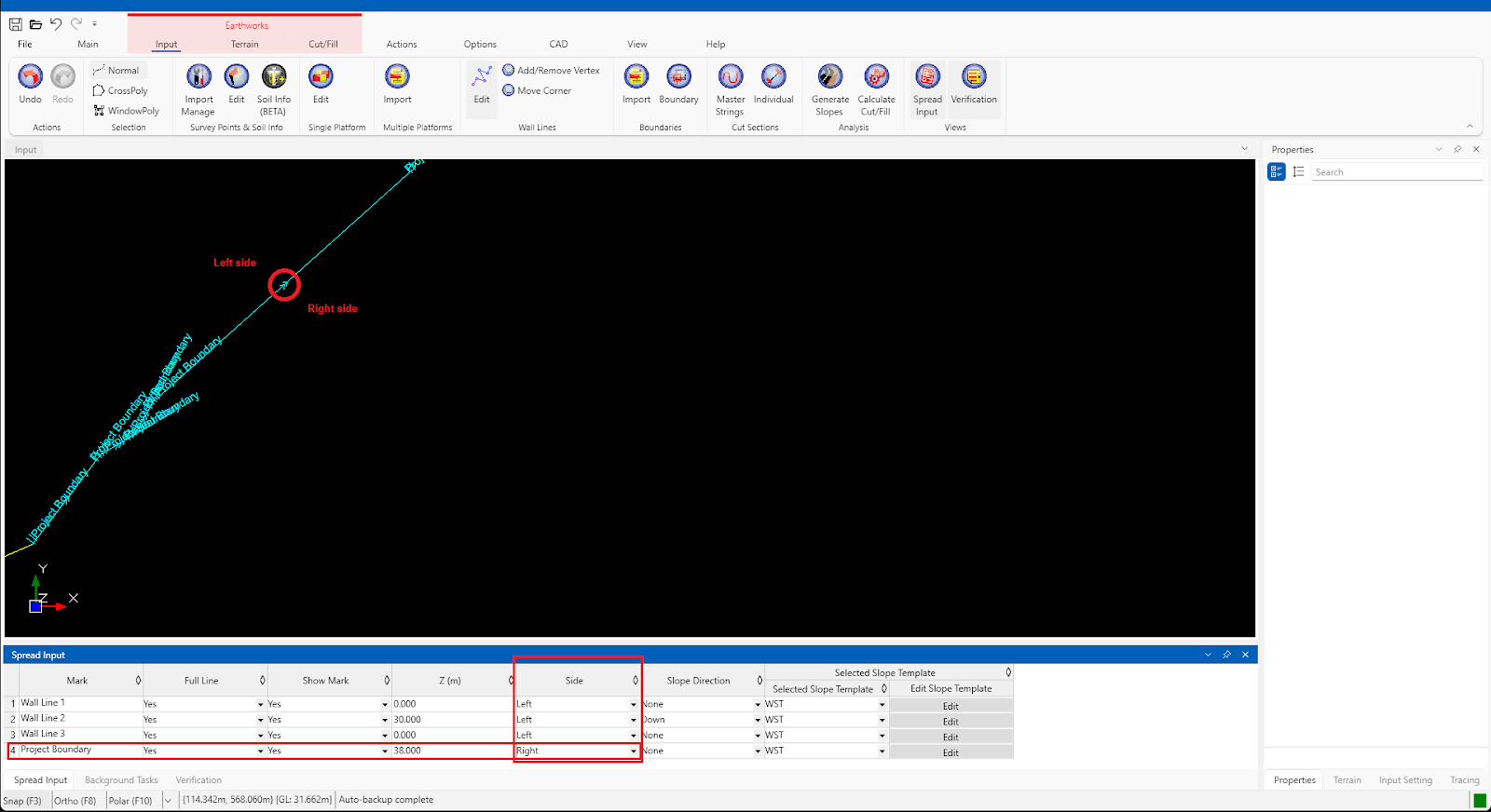
Shown below is a project boundary [red line] where its boundary has a slope. So how to use this wall line to create a slope?

- Create a wall line at the end of your boundary. In the spread input, insert the wall line height in the Z (m) column.
- Take note of the direction of the arrow
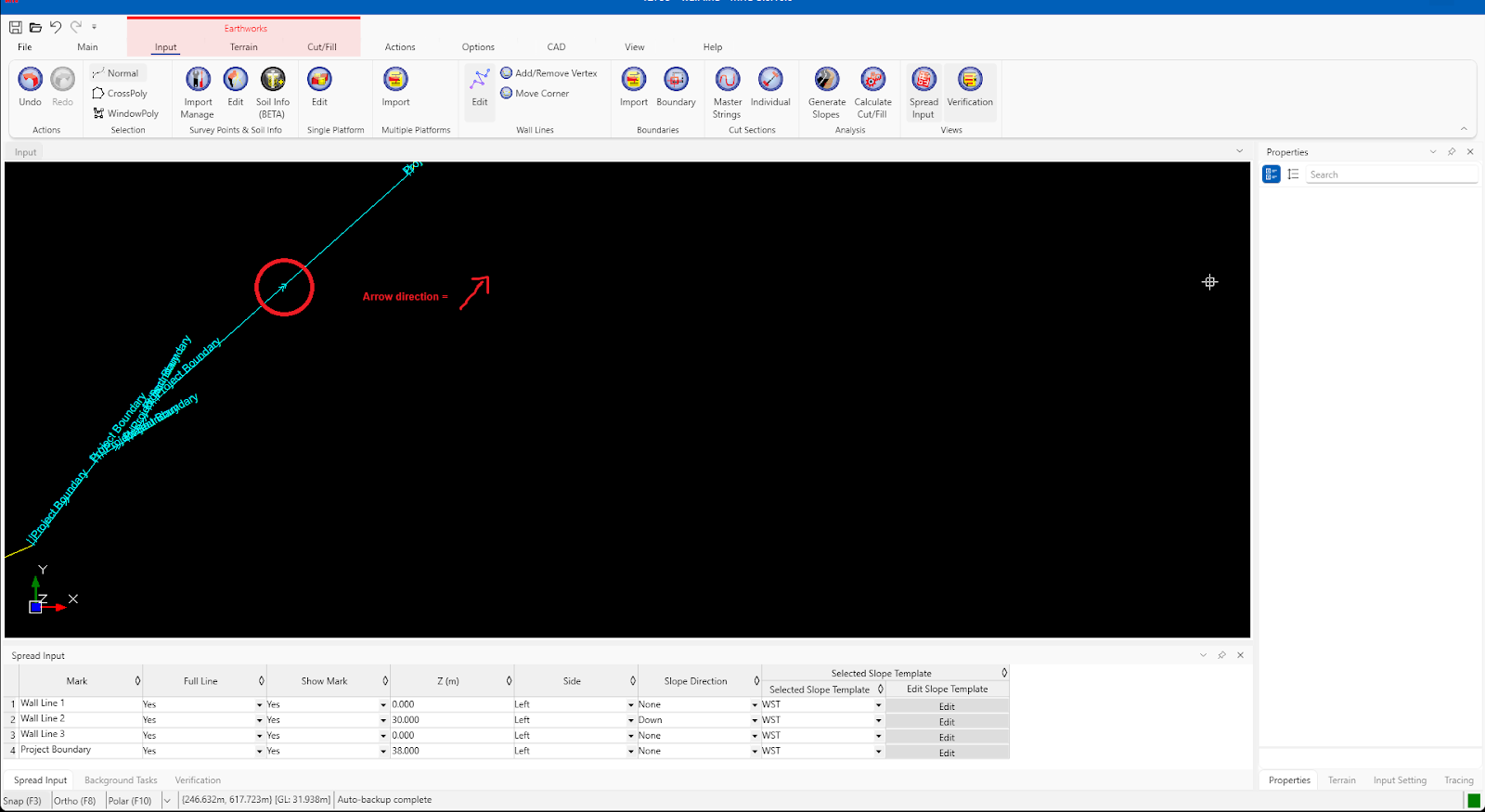
- Choose which side of the wall line the slope will be generated/created:
- Right = Right side of the arrow direction
- Left = Left side of the arrow direction
We will create a slope at the right side of the wall line. So change its side to ‘Right’ in the spread input
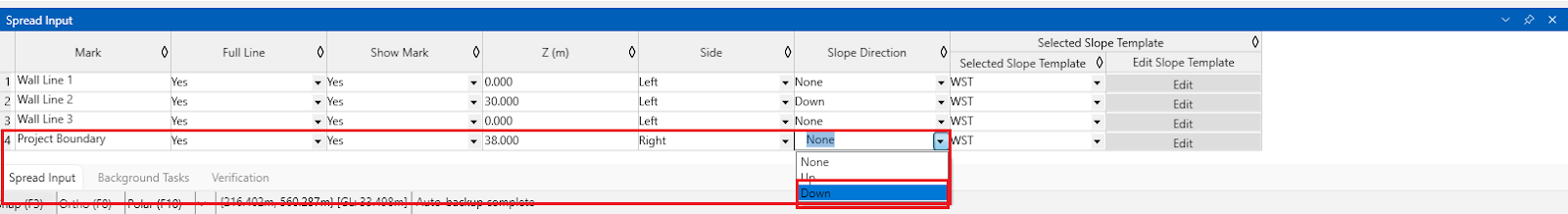
- In the example image, its slope is generated downward, so we will change our slope direction in the spread input to ‘Down’.
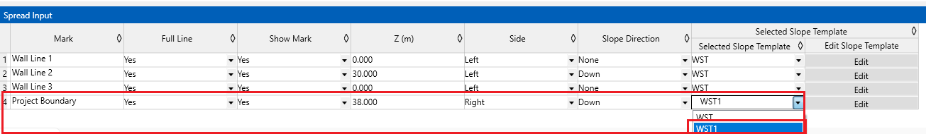
- If you want to create your own slope dimension, then you can use the slope template feature. Once you have done configuring your slope template, then you can select the template in the spread input to generate the slope.
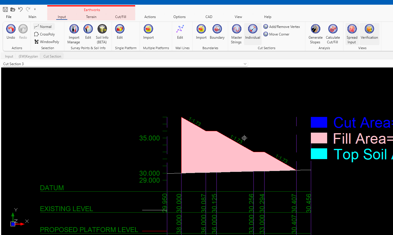
- Create a cutline to view its cut section.
Create a retaining wall at toe slope #
In the following blog post here, the step is to use a boundary to create a retaining wall at the toe slope. However, there are two disadvantages to using this method:
- If the platform with the retaining wall at its toe slope is in another bigger boundary, then slope generation can’t be continued since the boundary is overlapping
- If the user only wants to create a retaining wall along one edge of the platform, and the slope at another edge will continue till they reach the ground, then the usage of the boundary is not a valid option
So how to use a wall line to create this retaining wall at the toe slope along the selected edge only? The step is almost similar to the boundary’s:
- Generate slope so that we can trace which slope to create a wall line
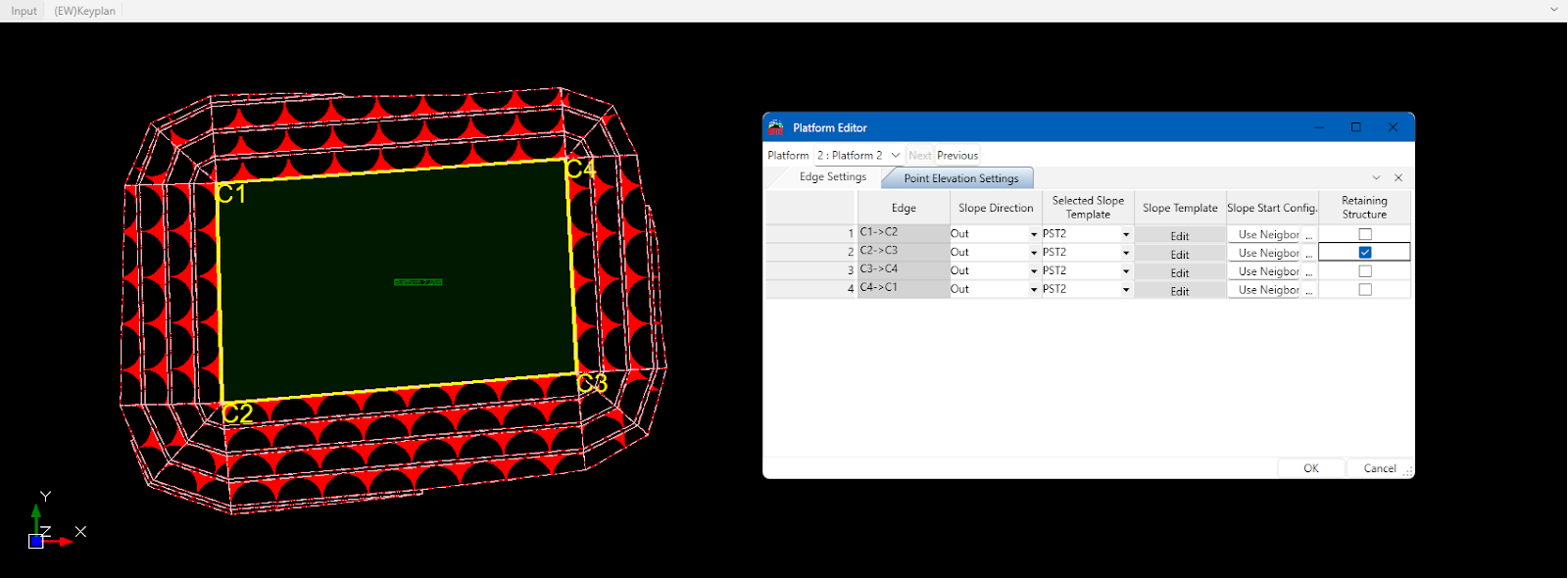
- We will create a retaining wall along C2->C3 edge after its second berm. Double-click the platform to open the Platform Editor and tick Retaining Structure for edge C2->C3.
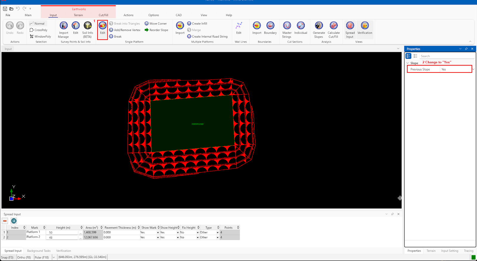
- Activate the previous slope feature. Go to;
Earthwork > Input > Single Platform > Edit > RHS Panel > Properties > Previous Slope == Yes
- Using the wall line, trace the second berm of the slope. Make sure to press the ‘SHIFT’ key simultaneously when creating a vertex point
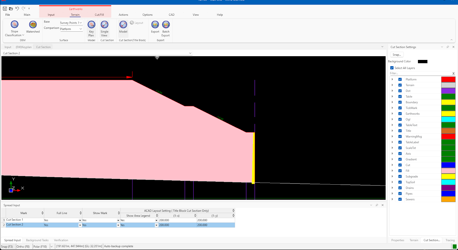
- Create a cut line across the platform to see the retaining wall after the second berm. Generate slope first before viewing its cut section
Create slope from Boundary #
Your project boundary also generates slope? Use wall line to replace your project boundary and create a slope from there.
- Trace the boundary using the wall line
- Repeat the step from here
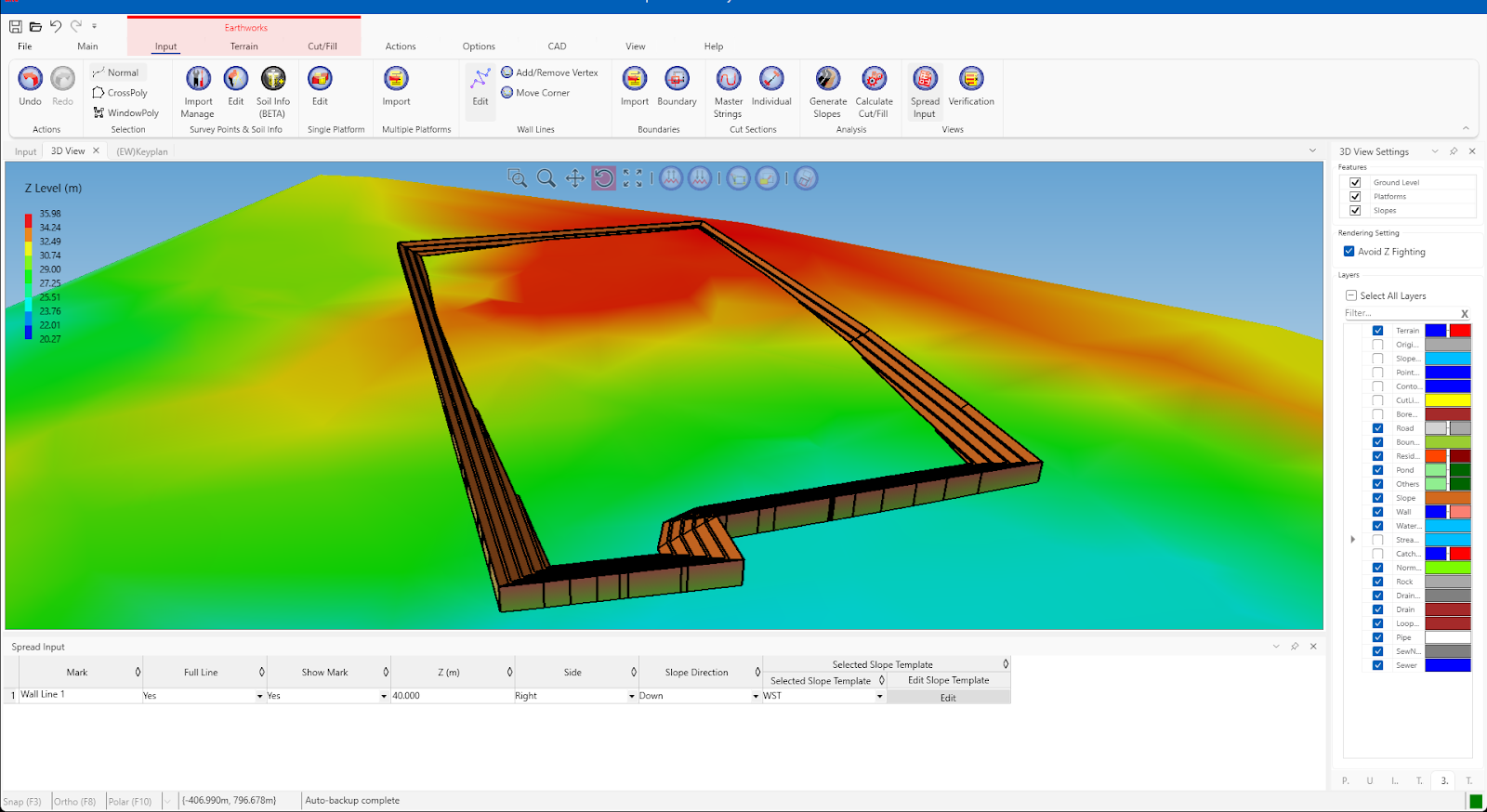
Shown below is the slope generated from the wall line in 3D view

I’m the Benevolent Dictator for Life for MiTS Software cum Editor of this website. Read more here.
You can also contact me at soonhui@mes100.com


