In MiTS 2, we do have several types of road width entities which can be added to your road. In this blogpost, we will focus more on how to use the cutside drain and fillside verge. We will create a project file which will produce the same cross-section as per required in Typical R1 Standard Road Cross-Section. Before we proceed to the example, we will first need to understand what is cutside drain and fillside verge.
What is a cutside drain? #
You can refer to our website here to understand better on what is cutside drain.
What is a fillside verge? #
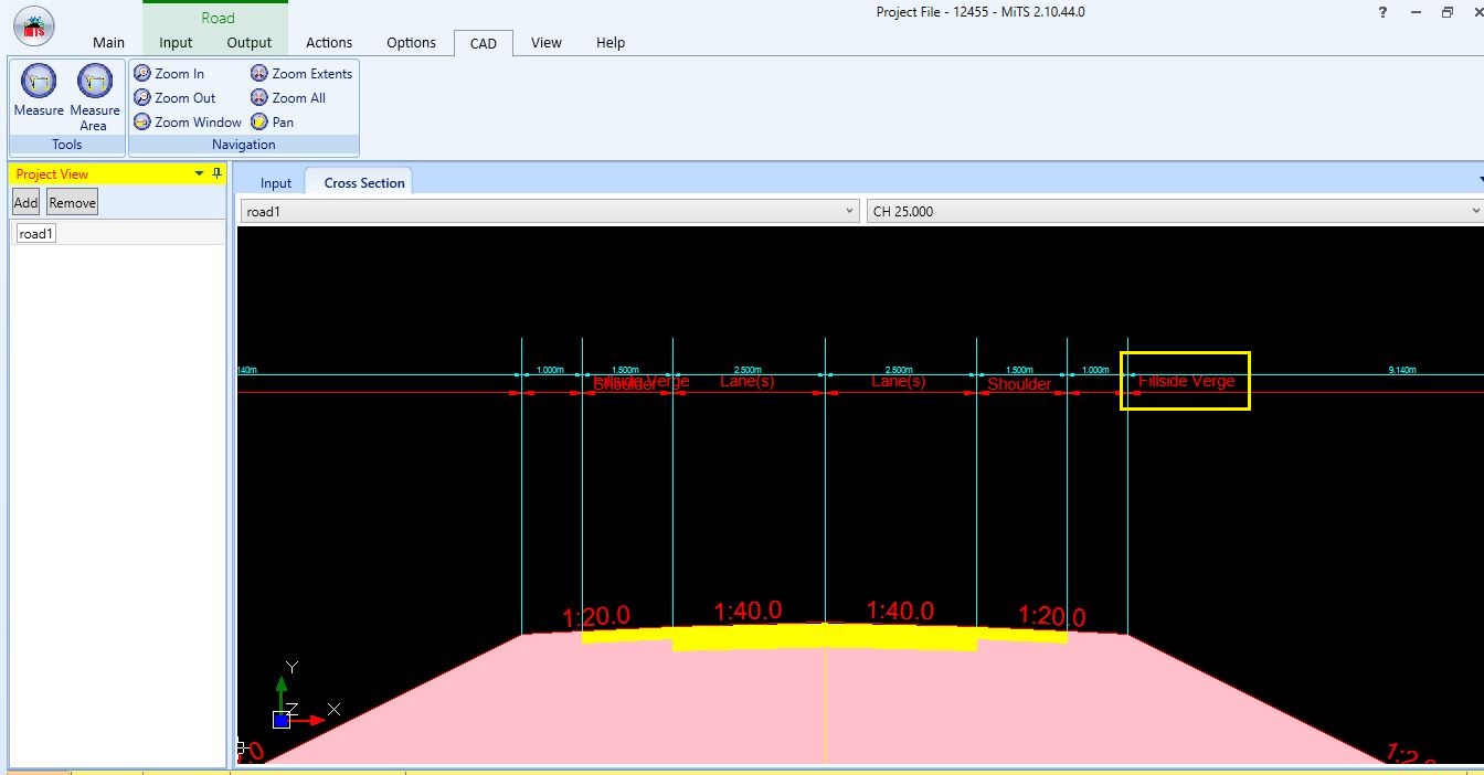
Fillside verge is a verge that is only visible at the fill area. The zoom-in image below shows the whereabouts of the fillside verge at the fill area.
Adding Cutside Drain and Fillside Verge in Road Width #
We will now proceed to design our road cross-section as per Typical R1 Standard Road Cross-Section. You can refer to the JKR guideline for Typical R1 Standard Road Cross-Section here.
Project file here
Step 1: Add road width entities; #
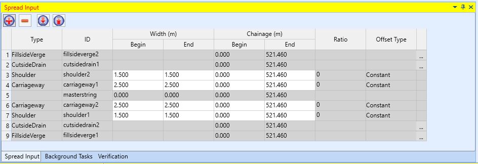
- In the “Spread Input” window, click ‘+’ button on the upper right corner, then add the cutside drain in each left and right of the road.
- To add the cutside drain, change the type to cutside drain first
- Click “Add” button after making sure it is right side.
- Then change the side to the left and click “Add” button again.

- Repeat the same step for fillside verge.
- Image below shows how the “Spread Put” windows should look like after adding all the road width entities
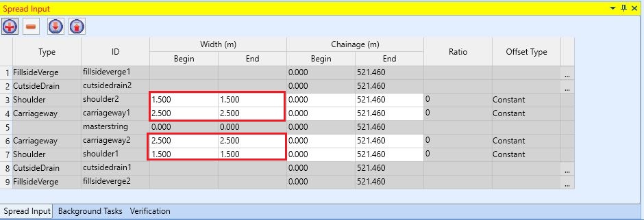
Step 2: Adjust carriageway and shoulder #
- Based on the cross-section from Typical R1 Standard Road Cross-Section, properties for our carriageway and shoulder are as follow;
| Width | Gradient | |
| Carriageway | 2.5m | 2.5% |
| Shoulder | 1.5m | 5% |
- Go to spread input to adjust the road width
- Go to properties tab at the RHS panel to adjust the gradient for the shoulder

Step 3: Adjust cutside drain #
Under the cutside drain, there are another two drains which are “Cutside Drain” and “Toe Drain”. Cutside drain will appear at the cut area whereas Toe drain will appear at the fill area.
- Go to spread input, in the last row for cutside drain, click the three-dots button
- Edit the cutside drain properties as per JKR R1 Standard
- Click “OK”
- Edit another cutside drain properties
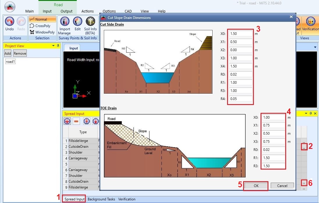
Based on the cross-section from Typical R1 Standard Road Cross-Section, properties for our Cutside Drain are as follow;
| X0 | X1 | X2 | X3 | X4 | R0 | R1 | R3 | R4 |
| 1.50m | 0.50m | 0.00m | 1.00m | 1.50m | 0.02 | 1.00 | 1.00 | 0.05 |
Since we do not have the Cutside Drain details, we will assume the dimension
We will design the verge at cut area, using the “X4” and “R4” element under the cutside drain
Whereas, the properties for our Toe Drain are as follow;
| X0 | X1 | X2 | X3 | R0 | R1 | R3 |
| 1.00m | 0.75m | 0.500m | 0.75m | 0.02 | 1.50 | 1.50 |
Step 4: Adjust fillside verge; #
- Notice that the verge location and dimension is different at the cut and fill area. Hence, for the cut area, we will use elements ‘’X4” and “R4” in the cutside drain as per mentioned in Step 4. Whereas for verges at the fill area, we will use this fillside verge.
- Go to spread input, in the last row for fillside verge, click the three-dots button
- Edit the fillside verge properties as per JKR R1 Standard
- Click “OK”
- Edit another fillside verge properties

Based on the cross-section from Typical R1 Standard Road Cross-Section, properties for our Fillside verge are as follow;
| Width | 1000mm |
| Gradient | 5% |
Hence, the input in our software will be as follow;
| X0 | 1.00m |
| R0 | 0.05 |
Step 5: Add vertical alignment; #
- Refer here to add vertical alignment
Step 6: Generate slope and view cross-section; #
- To generate the slope, just click the “Generate Slope” button in the “Analysis” window.
- Then click “Yes”.
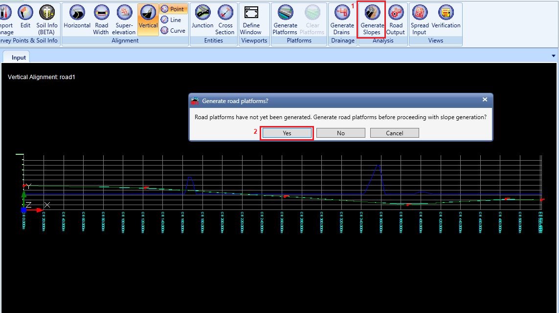
Image below shows the generated slope

- After the slope has been generated, go to
- “Output” > “Single View” in “Cross Section” > Choose which road to view > Choose which channel to view
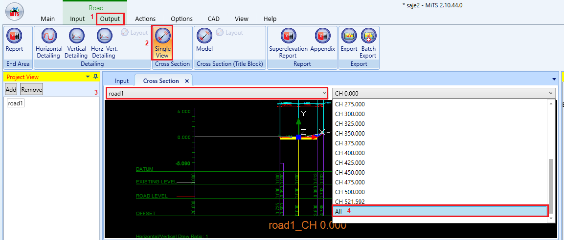
In this example, Refer to CH 25 as Fill area and CH 400 as Cut area
| Channel | Full View | Zoom-in |
| CH 25 | 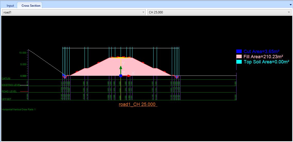 | 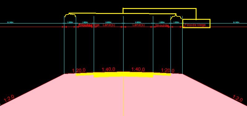 |
| CH 400 | 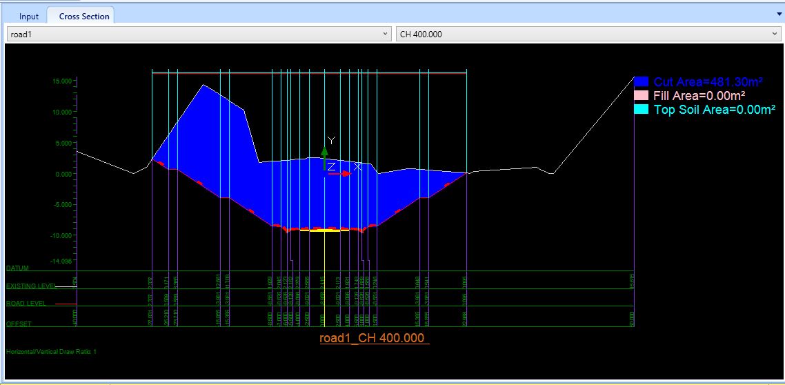 |  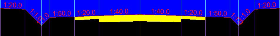 |
Output from MiTS and JKR R1 standard cross-section #
| Entities | MiTS 2.10.44.0 | JKR R1 |
| Fill Area | | 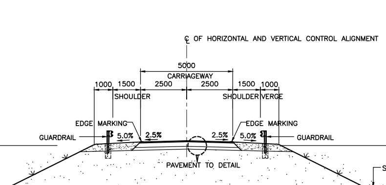 |
| TOE Drain | 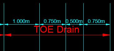 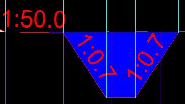 | 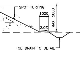 |
| Cut Area | | 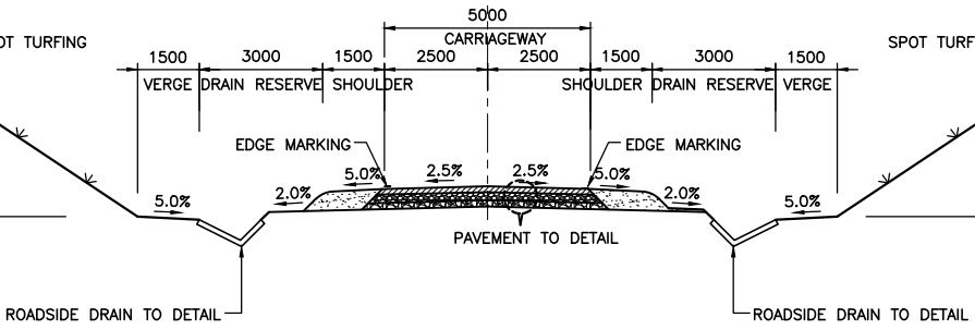 |

I’m the Benevolent Dictator for Life for MiTS Software cum Editor of this website. Read more here.
You can also contact me at soonhui@mes100.com


