Introduction #
Just the other day we received an interesting query from one of our users, Ms. Izzah from WKL.
She found that the EW3D– the predecessor to MiTS 2– gave different cut and fill results with the results obtained by another contractor using Civil 3D. There are two OGL ( OGL 1 and OGL 2), and one As-Built (ABL) in the project files.
Checking Earthwork Computation in MiTS 2 #
Since the Earthwork module in MiTS 2 is an upgraded version of EW3D, we are planning to compare the earthwork computation using MiTS 2. We requested Ms Izzah to share her EW3D project file, and the Civil 3D file from the contractor. To check further, we use the MCIntegrator feature in MiTS 2,which allows us to integrate our project file with Civil 3D.
Checking Earthwork Computation in Civil 3D #
Civil 3D was proven to give quite a close result with MiTS 2. But this time, we also find that the Civil 3D yielded different values when compared to both MiTS 2 and EW3D.
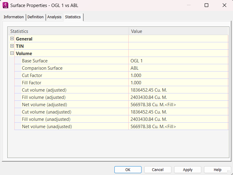 OGL 1 and ABL (Case 1) | 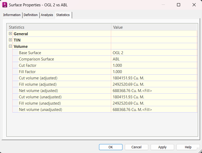 OGL 2 and ABL (Case 2) |
New Feature in MiTS 2 #
In MiTS 2, there are two new features which the settings of these features will greatly affect the earthwork computation. The two features are;
- Use all Survey Points: Yes/No
- Alpha value settings
Use All Survey Points Settings #
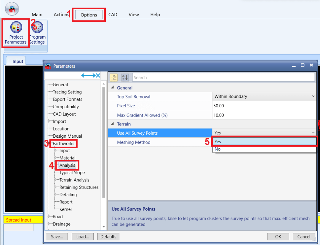
First, we changed the Use all Survey Points to Yes for both cases. You can find this setting by going to;
Options > Project Parameters > Earthworks > Analysis > Use All Survey Points: Yes
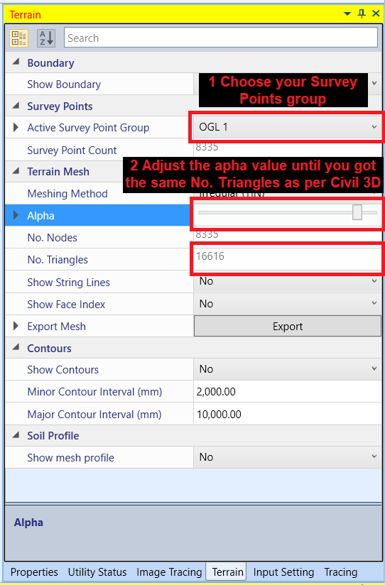
Alpha Value Settings #
Next, we change the alpha settings for every survey point group. What is the alpha value we should use? This alpha value provides granular control for the users to include and exclude the ground levels, depending on the user’s engineering judgement on how dense the surveyor points are necessary in order for accurate cut fill calculation. Hence, there is no right or wrong alpha value settings. You can see the image below to see the comparison on the triangulation of our survey points when we use minimum and maximum alpha value. When we use minimum alpha value, the triangulation will only include the area where there are survey points. Whereas when we use maximum alpha value, it will cover a larger area.


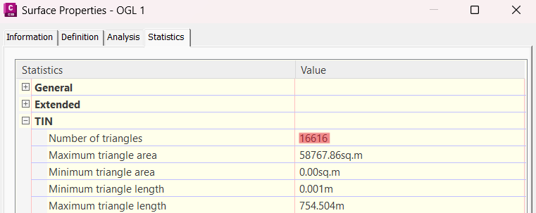
Since we are using Civil 3D as our benchmark, we will set the alpha value in MiTS until we get the same number of triangles as per Civil 3D. Observe images below which highlighted the number of triangles used in Civil 3D and MiTS 2.
| Civil 3D | MiTS 2 |
 |  |
 |  |
 |  |
Output from Civil 3D and MiTS 2 #
After making sure that we are comparing apple-to-apple between Civil 3D and MiTS 2, we proceed to calculate the cut/fill volume using the DTM Method. From the earthwork computation we got, the output we have from Civil 3D and MiTS 2 are nearly identical with only less than 0.4% discrepancy.
| Civil 3D | MiTS 2 (Alpha adjusted) | MiTS 2 (100% alpha) | |
|---|---|---|---|
| OGL 1 vs ABL | |||
| Cut volume | 1836452.45 m³ | 1829313.36 m³ | 1182482.03 m³ |
| Fill volume | 2403430.84 m³ | 2394955.70 m³ | 1151167.10 m³ |
| Net volume | – 566978.38 m³ | -565642.34 m³ | 31314.93 m³ |
| OGL 2 vs ABL | |||
| Cut volume | 1804151.93 m³ | 1797422.89 m³ | 200052.91 m³ |
| Fill volume | 2492520.69 m³ | 2484382.56 m³ | 123438.71 m³ |
| Net volume | – 688368.76 m³ | -686959.67 m³ | 76614.21 m³ |
You can see from the above table how big the effect of unadjusted alpha value will have on the cut and fill volume.
The tremendous effect of Alpha Value #
It is clear from the above, in order to the comparison between Civil 3D and MiTS 2, it’s imperative that you get the Alpha value– a proxy to the actual As-Built area under comparison— adjusted, so that the final As-Built Area under comparison must be exactly the same between Civil 3D and MiTS 2. If one fails to get the As-Built area to be the same, then the cut and fill volume will never be the same, due to the extra triangles.
Note that you can only adjust the Alpha value in MiTS 2, but not in Civil 3D.
Back to the above original case, it is found that the huge discrepancy was due to that in EW3D the Alpha value was set to 100%, and hence the comparison was not done with the same As-Built Area between EW3D and Civil 3D. As a workaround we suggested that the user draws boundary along the desired As-Built comparison area, and only compare the cut and fill within those boundaries. This will also solve the issue.
Conclusion #
In conclusion, the study on alpha value’s impact on earthwork computation revealed significant insights. Initial comparisons with the unadjusted Alpha value showed an unacceptable 83.94% discrepancy in net volume between two cases. However, further investigation with the proper adjustment of the alpha value, the difference in cut and fill volumes are properly minimized.

I’m the Benevolent Dictator for Life for MiTS Software cum Editor of this website. Read more here.
You can also contact me at soonhui@mes100.com


