Users are able to create a slanting platform by either specifying the elevation by points, or by edges.
Specifying Platform Elevation by Points #
Specifying platform elevation by points will be very useful if the platforms are irregular shapes. Unlike MiTS 1, users are restricted to only parallel edges, which may become a hassle for them to readjust the platform shape.
For example, the elevation for the platform below is slanting downwards towards right. To create as such, you can assign the corners with respective elevation.
Steps:
- Double click the platform to prompt the Platform Editor.
- Define the elevation as per image below (C2, C3, C4 and C5). While the rest of the corners, change the Height Method to Interpolated to allow software to interpolate the elevation based on their nearest height.

3. Then, click OK.
4. Check the elevation in the cut section.

Another way of creating a slanting platform other than specifying the elevation by points is to assign it by edges, which is explained in the next section.
Specifying Platform Elevation by Edges #
If the platform edges are parallel to each other, users are able to specify the elevation from one edge to the opposite edge.
For example, the starting edge (elevation 50 m) is slanted towards the end edge (elevation 54 m).

If the edges are parallel, users can specify the elevation by edges. Double click the platform to open the platform editor. Then insert the elevation. The parallel edges will be indicated by the same row colors.

Another alternative to create the slanting platform is by specifying the gradient in percentage. “Break” function is involved in this process, which will be explained in the Section (iii).
Specifying Platform Elevation by Gradient #
Users now can create a slanting platform with a certain gradient by using the Break function in Earthworks. It is also helpful if you are imitating a road slope cross section in Earthworks (ie -2.5% cross section gradient).

Example for slanting platform with 2.0% gradient goes upward:
- Create a platform
- Click “Break”
- Choose a starting edge (Example C1 > C4 is the starting edge)
- Click the edge (C1 > C4), the starting edge of the first segment is indicated with Blue highlight and purple highlight is the starting edge of the second section.

5. Assign the gradient in the Platform Settings

6. The cut section of the platform can be viewed in the Cut Section Terrain tab

Second situation is when road design is created in the Earthworks module and users want to imitate the road cross section. It would be easier if the gradient of the cross section is directly assigned rather than to assign elevation of each edge which has to be calculated beforehand.
Example of creating road cross section in Earthworks(2.5% upwards and 2.5% downwards:
- Create a platform for road
- Click Break
- Given -2.5% gradient for normal crown. Choose a starting edge (Example C4 > C3 is the starting edge)

4. Click the edge (C4 > C3), the starting edge of the first segment is indicated with Blue highlight and purple highlight is the starting edge of the second section.

5. Assign the gradient in the Platform Settings

6. Create a cut section across the platform

7. View the cross section in Cut Section Terrain

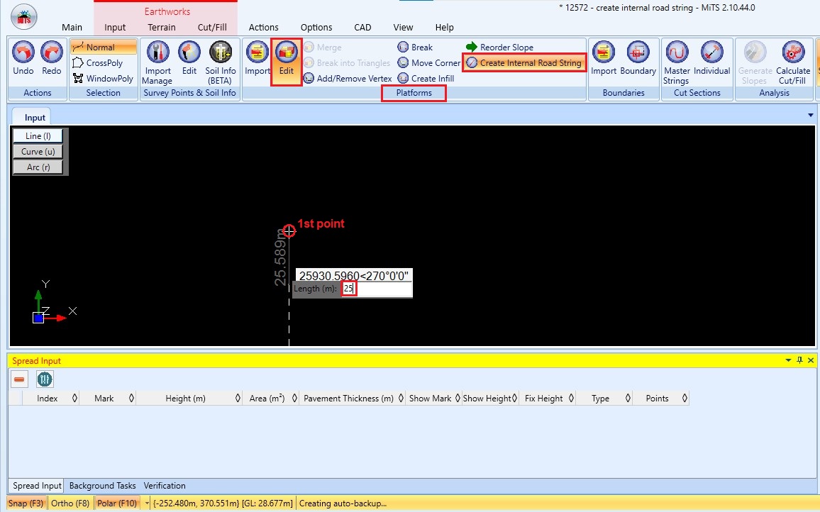
Specifying Platform Elevation by Create Internal Road String #
Users can now create a slanting platform using “Create Internal Road String” function. To use this function;
- First click the “Edit” and “Create Internal Road String” button in the “Platforms” panel. Then specify the first point and drag the cursor for the next point or you can straight input the distance for the second point and press the “Enter” key. This will create a line that serve as a middle-line for your platform.
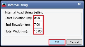
- A window as per the image below will appear immediately after you press the “Enter” key. Insert the setting for your internal road string. Then, click “OK”.
- Check the elevation in the cut section.


I’m the Benevolent Dictator for Life for MiTS Software cum Editor of this website. Read more here.
You can also contact me at soonhui@mes100.com


