While navigating or zooming on the Input Screen of a large-scale project, users might experience a noticeable slowdown in the speed or responsiveness of the MiTS program. The decrease in speed becomes more pronounced when dealing with projects that involve large CAD files as part of the tracing.
The term “large CAD files” here does not necessarily imply that the drawing should have visible thousands of entities within it. It can also refer to sparse-looking drawings that only consist of simple entities like points and polylines; drawings with numerous hidden entities which you can’t see unless you turn them on.
So, how can we optimize the drawing? #
The key to overcoming lagging or slowdown issues in general – a clean drawing. This involves decluttering or cleaning up the drawings by removing unnecessary or unused entities (objects, layers, blocks, etc); leaving behind smaller sized files.
In MiTS, the optimization of the drawing files can be achieved through the use of the ‘Optimize’ feature. This option is available when uploading drawings as tracing files, allowing users to efficiently clean up the CAD files, improving the performance of the software.
More technically, the optimize function removes unnecessary blocks and layers and thus freeing up memory, and also converting highly regular and numerous entities such as Points into a specific structure called Point Group. This will not only improve the snappiness of the program but also reduce the memory usage.
Outlined below are the steps, demonstrating how the mentioned feature can be utilized to reduce the size of tracing files in two occasions; (1)Uploading tracing with survey points in newly created project files and (2) uploading only the tracing files in existing project files.
Uploading tracing with survey points in newly created files #
Steps: #
- Survey Points & Soil Infor > Click ‘Import Manage’.
- Click ‘ACAD / TEXT / LiDAR’ > Open the selected drawing file.

- Click ‘Optimize’ > Select layers that represent the survey points.

- Click ‘Import’.
File Size: Before Optimize vs After Optimize #

Uploading only tracing files into existing files #
Steps: #
- At the RHS, click on Tracing Tab > Click Load
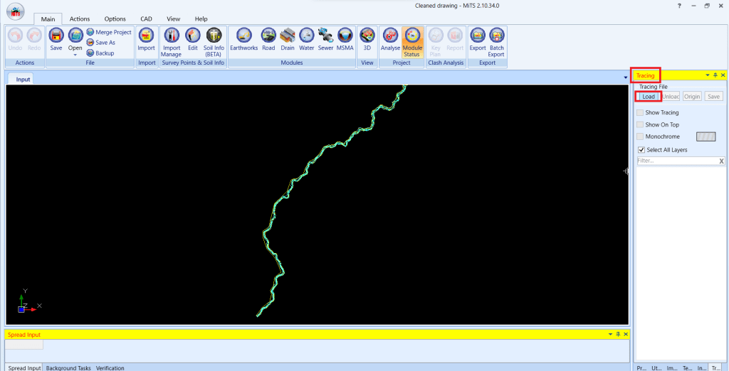
- Under Tracing model window, click on ‘Load’ to open the CAD file

- Click ‘Optimize’ > Click ‘OK’

File Size: Before Optimize vs After Optimize #

Use Native Font and Fallback SHX Font Option #
Use Native Font Option
If user still experience major lag or freezing while panning and zooming large tracing drawings in MiTS, it is possibly due to the drawing that uses some .shx font files that do not exist in the default VectorDraw Developer Framework (VDF) search path. So, the unreferenced .shx font files from the ACAD drawing are by default substituted with a ‘system fonts’ called TrueType Fonts (e.g.: Arial TTF font). Refer here to understand the difference between these two font types.
To cater this issue, user can tick ‘Use Native Font’ option that improves rendering speed by simplifying how the fonts are handled. The text might not look as sharp or fancy on the input screen. But performance is way better. (So it’s a performance vs. appearance trade-off.)
User can enable this option by following this steps:
- Check ‘Use Native Font’ box under Tracing Tab at Right Hand Side; or
- Options > Project Settings > Tracing Setting > Use Native Font > Set to ‘Yes’


Fallback SHX Font Option
In addition to the ‘Use Native Font’ option, we also introduced a ‘Fallback SHX Font’ in MiTS 3 as the default substitution which will ensure smoother navigation with the tracing drawing. In other words, with the implementation of this feature, you will have a faster loading process when you try to zoom and pan your modelling.
To change the fonts accordingly, users may follow the steps below:
- Go to Options > Machine Settings > Tracing File.
- Then, change the SHX font accordingly > Click OK

Comparing Function of Use Native Font on Large Tracing Drawing #
Disable ‘Use Native Font’ Option
Enable ‘Use Native Font’ Option
Enable ‘Use Native Font’ Together with ‘Fallback SHX Font’ Option
Enable ‘Fallback SHX Font’ Option Only
What can we observe from the four scenario clips?
Having both ‘Use Native Font’ and ‘Fallback SHX Font’ options significantly improve the speed of zooming and panning of the model. Whilst having only one of them enabled especially when the ‘Use Native Font’ option is disabled, we can still experience minor lagging with the large tracing drawing.
What is the difference between SHX font and TTF font? #
SHX font files are vector-based fonts that are primarily used in AutoCAD drawings. The fonts are lightweight, constructed using simple geometric shapes made up of points, lines and curves, which come together forming characters and symbols. Due to their simple structure, this makes SHX fonts ideal for technical drawings, as they load faster and require less computing power.
Meanwhile, TTF Fonts (also known as system fonts) are standard TrueType fonts that are installed in operating system (e.g.: Windows or MacOS). Common system fonts that we have definitely seen include Arial, Times New Roman, Calibri etc. TTF fonts are made of complex curves to define individual characters and symbols, making it suitable to scale up or down the font size without losing quality even in PDF of prints.
Due to its visual richness and intricacy, TTF fonts require more processing power to render. Consequently, when used in large quantities in CAD files, they can slow down screen performance significantly.
Comparing the optimized drawing #
In MiTS 2: Before vs. After #

MiTS 2 vs. Civil 3D #
Additionally, the performance evaluation of an optimized drawing with over 800,000 survey points in both Civil 3D and MiTS 2 are included. It becomes evident that in MiTS 2, the operations of zooming, panning and object selection exhibit faster speed.
Zooming Operations #

Panning Operations #

Object Selection #


I’m the Benevolent Dictator for Life for MiTS Software cum Editor of this website. Read more here.
You can also contact me at soonhui@mes100.com


