Previously, water reticulation analysis in our software only provides checking for Peak Flow and Fire Flow. Hence, when it comes to submission to the authorities, users have to manually compute and tabulate pipes and node details for the Average Flow.
This includes the schematic plan, where only for Peak Flow and Fire Flow are available in the software. On top of that, users also need to manually insert a summary table on the flow analysis in the schematic plan for submission purposes. These might be quite involved, requiring extra workaround and time from the engineers.
To solve these challenges, we’re pleased to announce new features in the latest MiTS 2.9.9.0 for water reticulation – Incorporation of Average Flow analysis and a more comprehensive schematic plan. With the new analysis feature, software will carry out checking for the average flow against maximum head loss and velocity limit (for pipes) and minimum and maximum residual pressure (for nodes), same as Peak Flow and Fire Flow.

Including Average Flow Analysis under Project Parameters

Parameters that Average Flow will be checked against
The details on the nodes and pipes for Average Flow (including Peak Flow and Fire Flow) will be tabulated under the Excel Report and Texual Report as an output once you have analysed. Definitely less time wasting and more time saving!
Excel Report Result with Average Flow Analysis #
Details (such as flow in pipe, velocity, head loss, and more) for each Average Flow, Peak Flow, and Fire Flow calculation can be viewed by clicking the bottom tab under the excel report. It should be noted that the average flow will not be generated if it is not included in the analysis under the settings for parameters.

Excel Report

Example of Pipes for Average Flow calculation

Example of Nodes for Average Flow calculations
Textual Report With Average Flow Analysis #
The output results of the Average Flow analysis will also be generated in the textual report for the pipes and nodes.


Schematic Plan Drawings Output #
Schematic plan of Average Flow, Peak Flow, and Fire Flow can be viewed by clicking the ‘Schematic Plan‘ icon under the Output tab. The schematic plan now not only includes the details on each node of the network, but also a flow analysis summary table. The summary table shows details on the elevation, water demand, HGL, and pressure for each node.
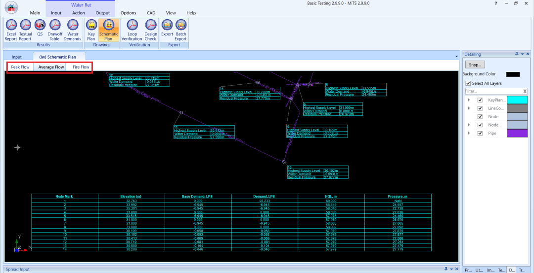
Schematic Plan for Average Flow Analysis
Bonus feature to the users, the summary table’s column can be sorted in ascending or descending manner by choosing the appropriate index and changing the setting under Project Parameters, just like in sewerage and drainage modules.


I’m the Benevolent Dictator for Life for MiTS Software cum Editor of this website. Read more here.
You can also contact me at soonhui@mes100.com


