With the new feature introduced in MiTS 3, Custom Element Editor, you can add the new, your own definition road components in MiTS as per your project design. Read also this post here to explore more on the difference between built-in elements and customize road width elements.
So, how to use this new feature? #
You can find the example project file here
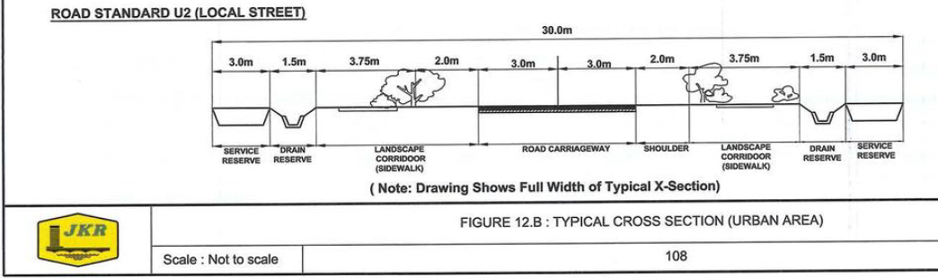
In this example, we are using the road cross section provided in Arahan Teknik Jalan ATJ 8/86 (Pindaan 2015), page 108 as a reference to design the road width element.
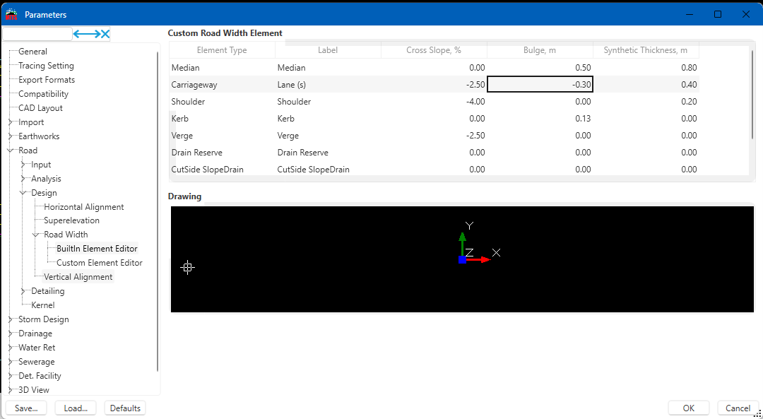
- To add a new element, go to Options > Project Settings > Road > Design > Road Width > Custom Element Editor
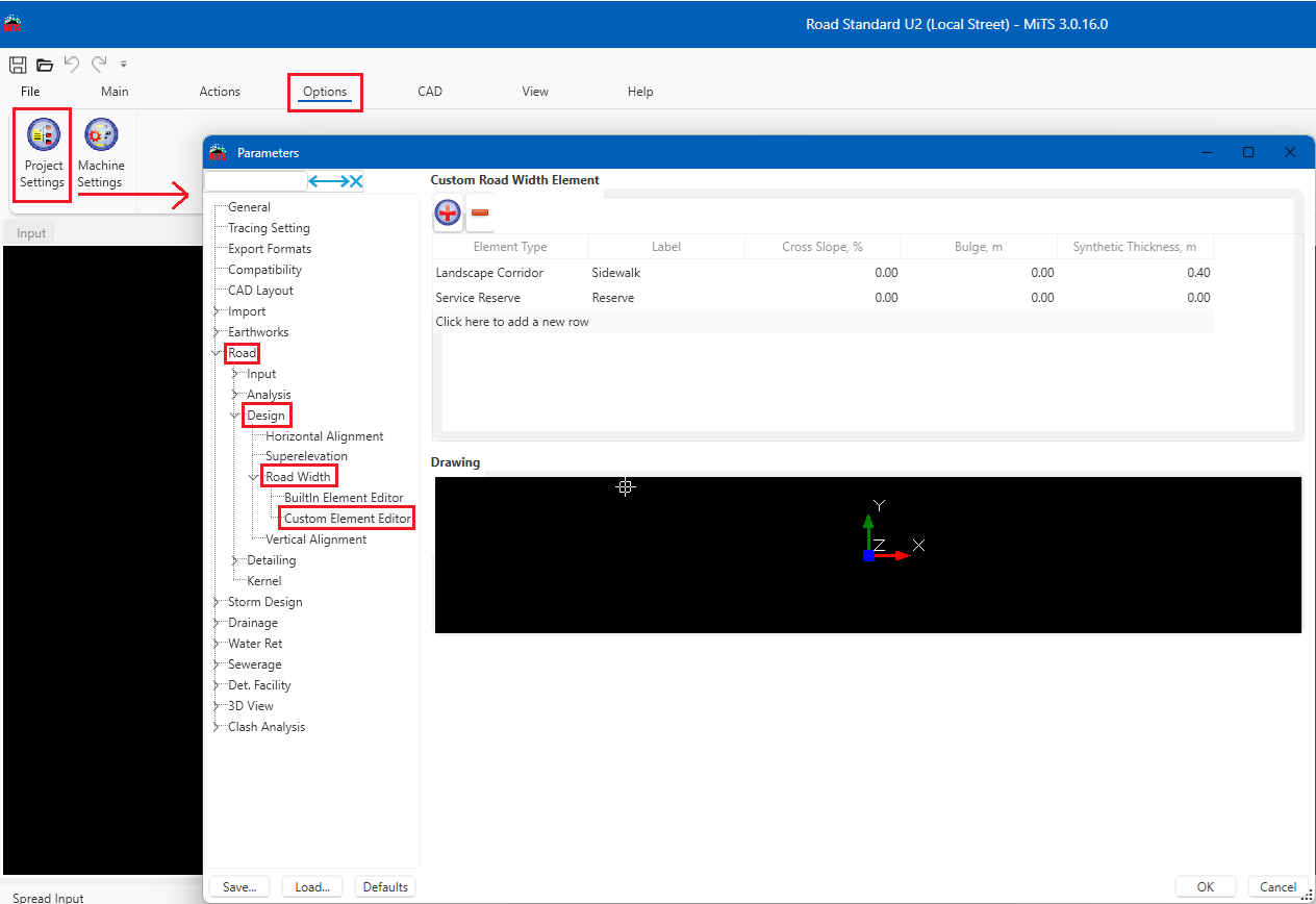
- In the element type, add an element that you want to create. Make sure to press ENTER once you are done inputting all the necessary data for the new element and then click OK
- Then, you can add the road width element as per the example from ATJ 8/86
- If you compare the cross section in MiTS with the example used, the drain reserve is placed after the shoulder where it should be after the landscape corridor
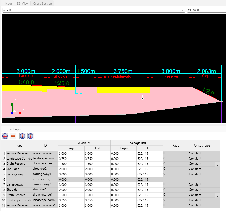
- Worry not, you can adjust their position by using the upward and downward arrow in the spread input
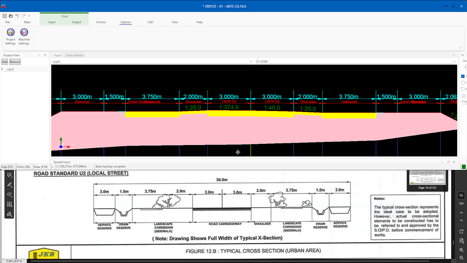
- Comparing the composition of the road width elements in MiTS 3 with ATJ 8/86, it is indeed a successful design
Custom Properties of Road Width Element #
There are 4 properties of a road width element which are cross slope, bulge, label and synthetic thickness. All of these 4 will follow the one you set in the project settings for your road design.
Bulge #
Bulge is an increment or decrement of an element’s elevation height. It will increase or decrease with respect to the neighbouring element. For example, you want to have a carriageway a bit lower than the median, so you put a -0.3m bulge for the carriageway in the project settings and design a 3-lane carriageway. You will see the carriageway is designed as a step in the cross-section.
Maybe the output that you imagine is the image 1 but instead, you got the later output.


To create the output as image 1:
- in the project settings, set the bulge as 0m for the carriageway
- Click on the carriageway1 row in the spread input
- Go to the ‘Properties’ tab at the RHS panel and insert -0.3 for the bulge

Label #
Label is the name of the element that will be shown in the cross-section. In your design, you might have a fast lane and a slow lane. So, to differentiate this type of lane, the easiest way is to label them respectively. Similar to the step to insert the bulge value, put the correct label for the lane in the RHS panel.

Synthetic Thickness #
Different types of lanes have different needs. The slow lane is usually for the slow driver and heavy-weight vehicle. Therefore, its subgrade and pavement thickness are thicker than the fast lane.
To adjust the thickness of the lane, you can use a similar step with the previous properties of the road width element, bulge and label.

Cross Slope #
Now you might want to edit the cross slope of certain elements. Elements that can be adjusted in their cross slope are the verge and custom element of road width. The step is similar to all other properties of the road width element, just click on the element and adjust its value in the ‘Properties’ tab of the RHS panel.


I’m the Benevolent Dictator for Life for MiTS Software cum Editor of this website. Read more here.
You can also contact me at soonhui@mes100.com


