Concepts #
In Civil 3D, managing the sizes and types of pipes and structures is essential for designing effective pipe networks. The Part Catalog and Parts List are key tools that help engineers select, organize and document components like pipes and structures. This article will explain the basic concept of Part Catalog, Parts List, Pipe and Structure, and guide you through the process of adding pipe and structure sizes to the Parts List in Civil 3D.
Part Catalog #
The Part Catalog is a collection of predefined parts that are used in the design and creation of storm sewer, sanitary sewer, or other pipeline systems. The catalog contains a wide variety of pipe sizes, materials and structures that you can use in your design. The catalog is customizable, and users can add new parts or modify existing ones to suit project-specific requirements.

Parts List #
A Parts List is a list of all the pipe network parts (such as pipes, structures and fittings) that are included in a specific design or project. Parts List is also a kind of Style, and so it is drawing-based. When you copy a drawing from one machine to another, it will be copied over, as the Parts List is embedded in the drawing. Parts List is essentially just a pointer to the Part Catalog ( which is the real content) so by itself it doesn’t have any concrete information. You need to have the Part Catalog on the local machine and set it correctly ( for the gravity network and for the pressure network) before you can use it.

Pipe #
Pipe refers to the components used to convey fluids or gases, typically in stormwater, sanitary sewer or water distribution systems. They are essential parts of pipe networks and are defined by their type (material), diameter, length and slope.
Pipes can be made of various materials, such as:
- PVC (Polyvinyl Chloride)
- Concrete
- Ductile Iron
- HDPE (High-Density Polyethylene)
Pipes in Civil 3D are not only physical objects but are part of the system being modelled for flow analysis, trenching or any necessary calculations. When added to a Parts List, the size and material of the pipe will be reflected in the project’s report.
Structure #
Structures are manmade components in a pipe network used to manage the flow of liquids or gases. Structure serves as junctions or transition points within the pipe network and may include:
- Manholes
- Inlets
- Catch basins
- Outfalls
- Valves
Structures in a pipe network are typically used for flow control, access points or to change the direction, size or material of the pipe. When modelling a stormwater or sewer system, you place structures where the flow must be diverted, stored or accessed.
| Term | Definition | Role in Design |
| Part Catalog | A library of predefined parts (pipes, structures, fittings) used for network design | Contains the actual dimension of a certain Pipe/Structure |
| Parts List | A table that lists the parts (pipes, structures) used in the network, including sizes and materials. It is a Style, and a pointer to Part Catalog | A pointer to the specific Part Size in Part Catalog |
| Pipe | The physical component that carries water, sewage or other materials between structures | The primary element of a pipe network, determining the flow of materials between structures |
| Structure | A component like a manhole, catch basin or junction that connects or interacts with pipes | Provides critical connections between pipes and helps manage or alter the flow of the network |
Adding Parts List and Part Family Generally in Civil 3D #
Gravity Network: #
For sanitary sewer and storm sewer, pipe and size can be added by:
- Set the Gravity Network Catalog, following the steps here.
- Go to the Modify tab, click the Pipe Network in the Design section, and you automatically go to the Pipe Networks tab.

- In the Network Tools section, click Parts List and select Edit Parts List. A ‘Parts List’ window is opened.
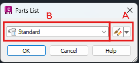
- To manage the existing part list, click the ‘drop-down’ button at ‘A’ and select ‘Edit Current Selection’. Expand ‘B’ and select any part list to be edited. (e.g., Storm Sewer).
- If you wish to create a new part list, select ‘Create New’ from the drop-down at ‘A’.
- Click the icon button at ‘A’ and the ‘Network Parts List – Storm Sewer’ popup window will be opened. For creating a new part list, a ‘Network Parts List’ popup window will appear and users can name the part list under the ‘Information’ section.
- Go to the ‘Pipes’ section, right-click the ‘Storm Sewer’ and select ‘Add part family…’ to open the ‘Part Catalog’ window.

- Choose the new pipe type to be added and click ‘OK’.

- To add size to the newly added pipe, right-click the new pipe and select ‘Add part size…’ to open the ‘Part Size Creator’ window.

- Adjust the parameter to be added or just tick ‘Add all sizes’ to add all sizes available in Civil 3D for the new pipe and click ‘OK’.

- Expand the newly added pipe to check the size added to its list.

Pressure Network: #
For water reticulation pipe/pressure network pipe, the steps are quite similar to the sanitary sewer and storm sewer pipe, except for setting up the catalog, which needs to be done on a Part List basis.
- Load the Pressure Network Catalog, followed by adding the pipe or structure materials as in here.
- Repeat steps 9 ~ 11 from the above to add the part sizes.
You may refer to the video below for a better visualization.
Set Part Catalog using MCIntegrator #
MiTS users can also use MCIntegrator to add/adjust Part Catalog and Parts List in Civil 3D.
- Go to the ‘MES’ tab and click the ‘Machine’ button in the ‘Parameters’ section to open the ‘Machine Settings’ window.
- Click ‘I understand, CONTINUE’ and a new window will open to set up your Network Catalog and Parts List.
- Click on the ‘Gravity Network Catalog’ at the ‘Network Catalog’ tab to configure the pipe catalog and structure catalog to be used in the ‘Pipe Network Catalog Settings’.

Editing Parts List using MCIntegrator #
- Go to the ‘Parts List’ tab and click on the ‘Gravity Parts List’ to adjust the network pipe and structure components to be used, following the steps in the section above (Refer to steps 3 ~ 11).
- The Pressure Network catalog selection and the Part List adjustment can be done by clicking ‘Pressure Part List’ and following the same steps here.

Note that once you are at the above stage, you can also “Add Part Family” to your new Parts List.
Troubleshooting: #
What if the catalog set is incorrect? #
Gravity Network (Sewerage & Drainage) #
Without a correct catalog set, the synchronization between MiTS and Civil 3D will FAIL.
The failure stemmed from the software’s inability to locate the correct components of the network (structures, pipes, fittings, etc.) that are added to the network’s part list.
A part list will contain important information, such as shapes, diameters, materials, etc. This information will not be available for the software to read and find its matches between the two software programs, as it is searching in the WRONG library.
Not only does it prevent synchronization, but it also restricts users from making any modifications to the network.
For further understanding of Civil 3D behavior when it comes to the network catalog, users may read the article here.
So, how to verify the active network catalog? #
Users can verify if the catalog in the drawing is correct by attempting to edit any of the components in the part lists, as shown below.
Step 1:
In the drawing, navigate to the MES Tab and click on ‘Machine’.

Step 2:
Click ‘I understand, CONTINUE’. Go to the Part Lists tab and click on Gravity Part Lists.

Step 3:
Select Parts List corresponding to your Network and click on the button at the side, as highlighted in the image below.

Step 4:
Under the Part Lists, select any of the pipes or structures listed. Right-click and click on Edit. We will receive errors mentioning that the software is unable to edit the network part.


Pressure Network #
For pressure networks, the error displayed above is not reproducible because the catalog is loaded on a per-part-list basis.
This means that the specific parts employed for the network are directly linked to the part list and not the active catalog set for the drawing.
Therefore, issues with the catalog are only possible if the catalog file itself is missing from the program directory: C:\ProgramData\Autodesk\C3D 2026\enu\Pressure Pipes Catalog\Metric
So, how to verify the active pressure catalog? #
Users can verify if the catalog in the drawing is correct by attempting to edit the part lists, as shown below.
Step 1:
In the drawing, navigate to the MES Tab and click on ‘Machine’.

Step 2:
Click ‘I understand, CONTINUE’. Go to the Part Lists tab and click on Pressure Part Lists.

Step 3:
Select the Part Lists and click OK. Users will receive the error message below.


Step 4:
Click Close, and the part lists will appear. Users will not be able to edit the part lists as the ‘Add Size’ and ‘Edit’ features are not available.


How do we set the gravity and pressure network catalog correctly? #
The catalogs (pressure and gravity networks) are usually located at C:\ProgramData\Autodesk\C3D 2026\enu
Detailed guides the gravity and pressure catalog and how to set them can be found here.

I’m the Benevolent Dictator for Life for MiTS Software cum Editor of this website. Read more here.
You can also contact me at soonhui@mes100.com


