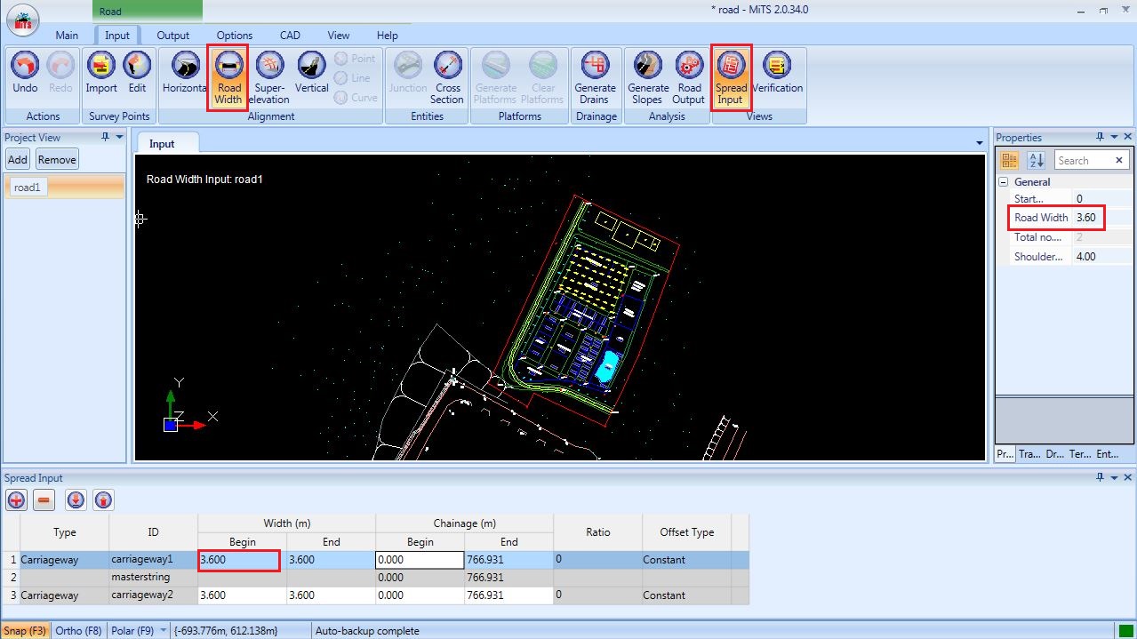
Road Width Input #
Click on the Road Width icon to input the number of lanes and width of the road.

Road width will be auto generated as default at both sides of MasterString. However, users are allowed to edit the width by selecting the “ Spread Input” and change the width to desired design width in the table, or change the width at Road Width Properties.
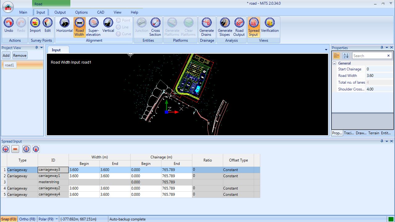
Add Carriageway #
Click the button at the Road Width Properties and New Road Offset box will be shown.

Users are able to change the width of the new carriageway and select the offset direction of ‘Left side’ or ‘Right side’ of Master String. Sub-rows are used to add additional rows for that particular carriageway mainly used for tapered road (please refer to section 5.4 below)

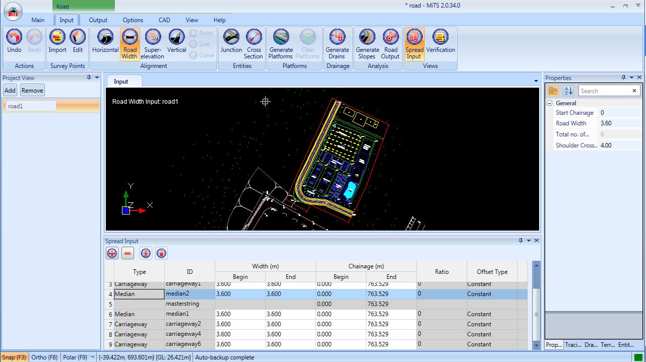
Add Median #
Select “ Median” from the button of New Road Offset box.

Users may input the desired median width and the offset direction.
Only one (1) road median is allowed at each side of the road.

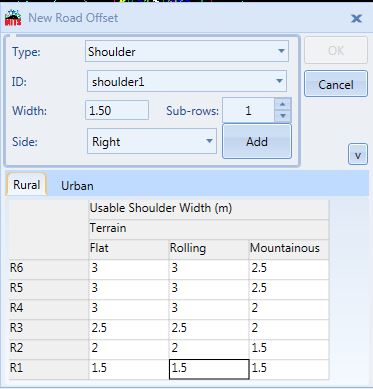
Add Shoulder #
Select “ Shoulder” from the button of New Road Offset box.

Select Rural or Urban standards.
Select the shoulder width based on the category of road and type of area/terrain with respect to the rural or urban standards.
Select the direction of offset.
Only one (1) road shoulder is allowed at each side of the road.
Add Kerb #
Select “ Kerb” from the button of New Road Offset box.

User may input the desired verge width and the offset direction
Only one (1) road kerb is allowed at each side of the road.

Click the . to change the kerb type.

The specification of the kerb are editable.
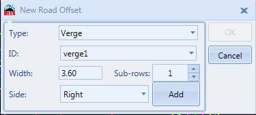
Add Verge #
Select “ Verge” from the button of New Road Offset box.

User may input the desired verge width and the offset direction
Only one (1) road verge is allowed at each side of the road.

Add Drain Reserve #
Select “ Drain Reserve” from the button of New Road Offset box.

Users may input the desired width and offset direction.
Only one (1) road drain reserve is allowed at each side of the road.

Click the . to change the drain type.

The specifications for all drain types are editable.
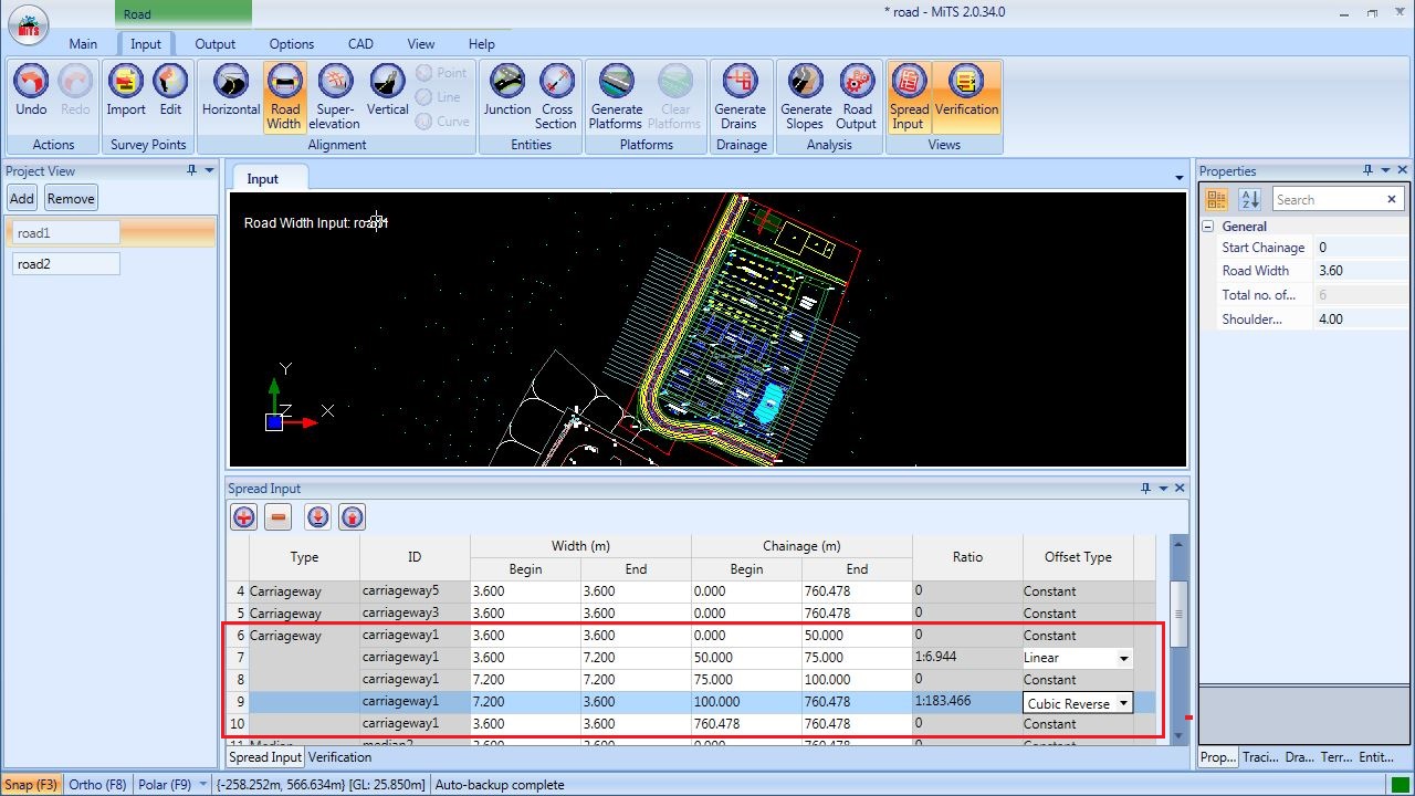
Add Tapered Transition #
To design a carriageway with vary of width, user may click button at Road Width Spread Input and select ID of ‘Carriageway’.

User may add the number of sub-rows accordingly and click the button.
Road width Properties Spread Input will allow users to design road widening by editing the begin/end width and begin/end chainage.
Users may also select Offset Type: Linear or Cubic Reverse Curve.
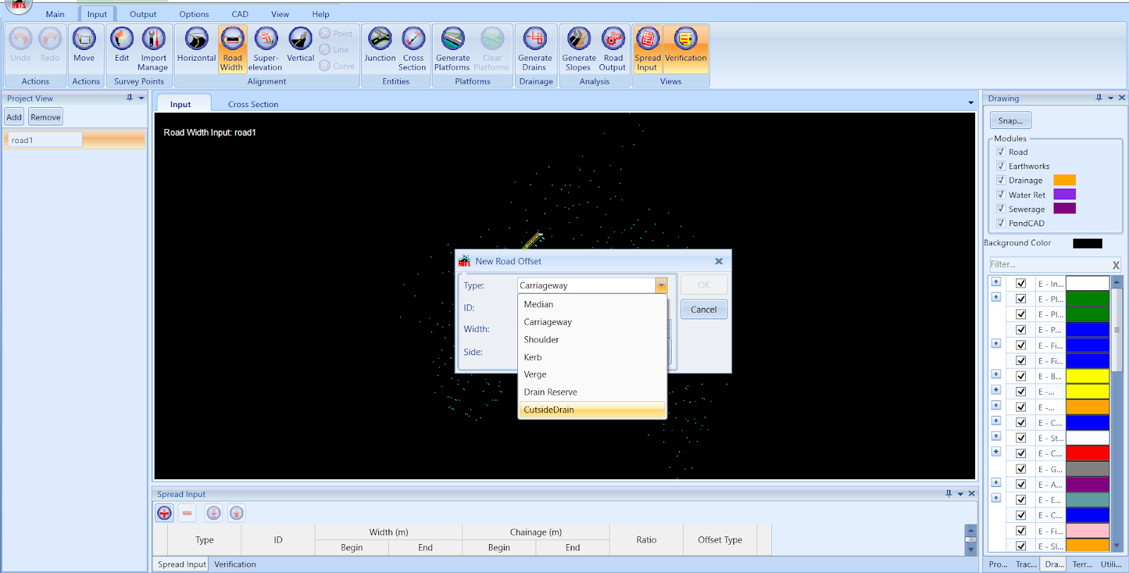
Add Cutside / Toe Drain #
Reference project file HERE (can only be downloaded/viewed by online-reading)
Refer blog post for more info on ‘Difference Between CutSide Drain and Drain Reserve‘.
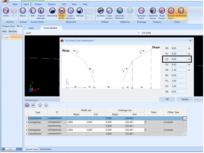
Add Cutside Drain #
Click on “Road Width > Spread Input > Click the plus button and choose cut side drain”
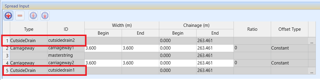
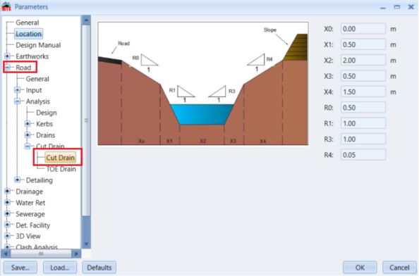
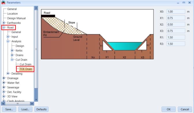
Change the dimension of the Cutside / Toe Drain #
Click on the three-dots to change the dimension of the cutside / toe drain and insert the dimension value in the editor box.

Second way of assigning the dimension is to change it in the Parameter Options, but bear in mind that the changes in the parameter will only be applied towards the newly created Cutside / Toe Drain.
Cross Section #
The cross section of the road can be viewed in the Output. Click “Output > Cross Section”
Based on the reference project file attached at the above, Chainage 0.000 is taken as an example, whereby the cutside drain is generated on the left side (cut area) and toe drain on the right side (fill area).
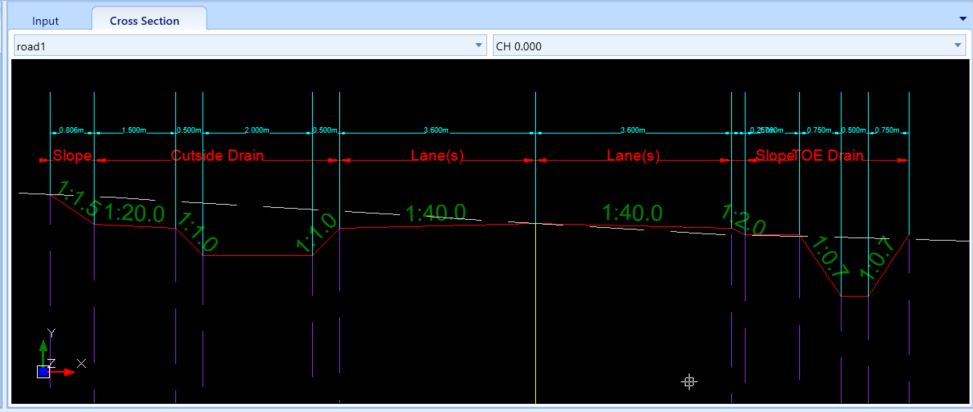
The dimension of the cutside and toe drain also can be adjusted in the spread input as explained in the above.
Any changes of the dimension in the spread input will be automatically updated in the cross section.

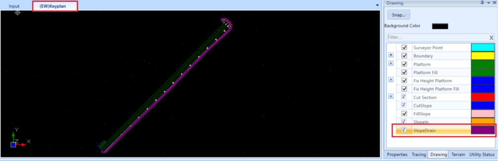
(EW) Keyplan #
Toe drain can be seen at the (EW) Keyplan after slopes are generated.
NOTE:
- Cutside / Toe drain size at Options > Parameter will only affecting the newly created toe drain (before slope generation)
- For cutside / toe drain that has been generated (after slope generation), the ‘cutside’ & ‘toe drain’ size can be adjusted at Road Width > Spread Input > CutsideDrain > click on ‘More options icon’ button.

I’m the Benevolent Dictator for Life for MiTS Software cum Editor of this website. Read more here.
You can also contact me at soonhui@mes100.com


