Analysis #
Analysis is divided into two which are Generate Slopes and Road Output.

Generate Slopes Analysis #
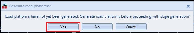
Before proceeding to Slope Analysis, Road Platforms have to be generated first. To generate road platforms, one needs to complete the Vertical design first. Or users can directly click on “Generate Slopes”. Messages asking to generate road platforms will appear and click on Yes to generate slope platforms. The platforms generated will be automatically synced in the Earthwork module.
The slope will be shown after analyzing.

To generate platforms, users can also manually generate the platforms by clicking Generate Platforms (refer to Section 9.4).
Road Output #
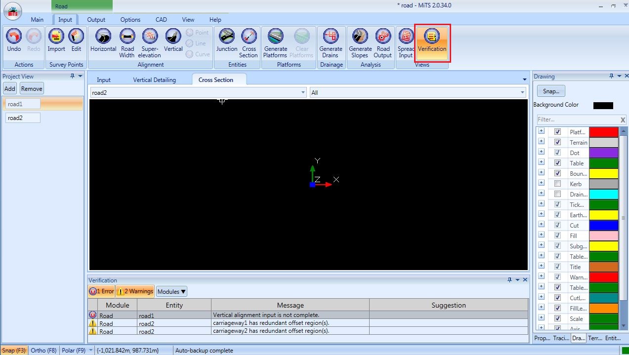
Complete road analysis consists of Horizontal Outline, Horizontal Plan, Vertical Detailing, Cross Section and Superelevation Report are shown after Horizontal, Road Width, Superelevation and Vertical design are completed. Click Verification Tab to view any incomplete inputs or any warnings before analyzing.
Horizontal Outline Road Output #
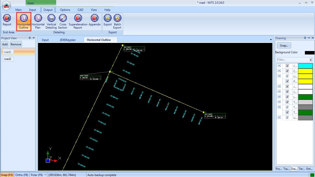
The table for each of the intersection points can be moved.
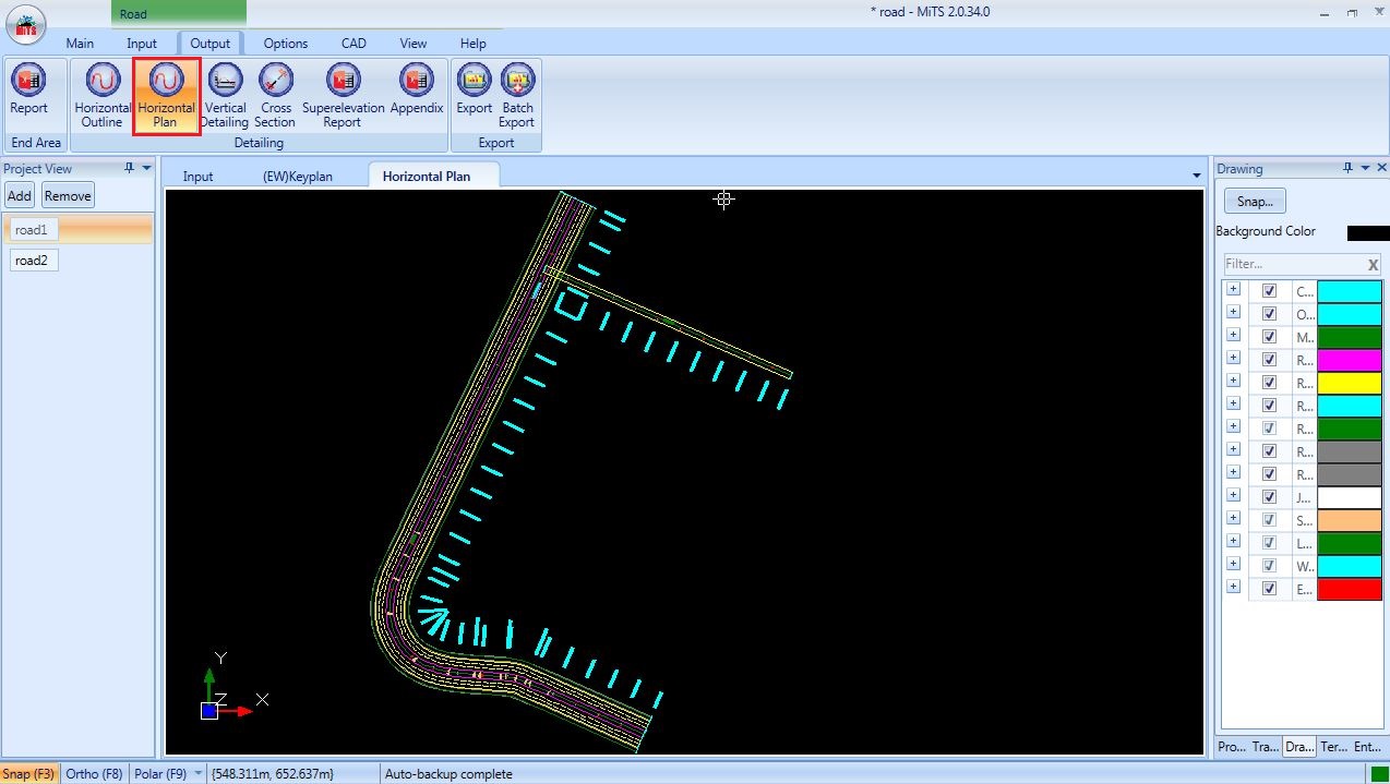
Horizontal Plan Road Output #
Horizontal Plan can be viewed by clicking on Horizontal Plan Output Tab.
Vertical Detailing Road Output #
To view the vertical detailing, click on Vertical Detailing Output tab. Select the road from the drop down list to view results of different roads. The scale of the vertical profile detailing can be set in Project Parameters.

Customize the indication of levels at Vertical Detailing Road Output #
Go to Parameters > Road > Detailing > Vertical > ‘Datum Grid Vert. Distance’ and ‘Cut Section Chainage Interval’

For example, Datum Grid Vert. Distance is 5m and Cut Section Chainage Interval is 25m
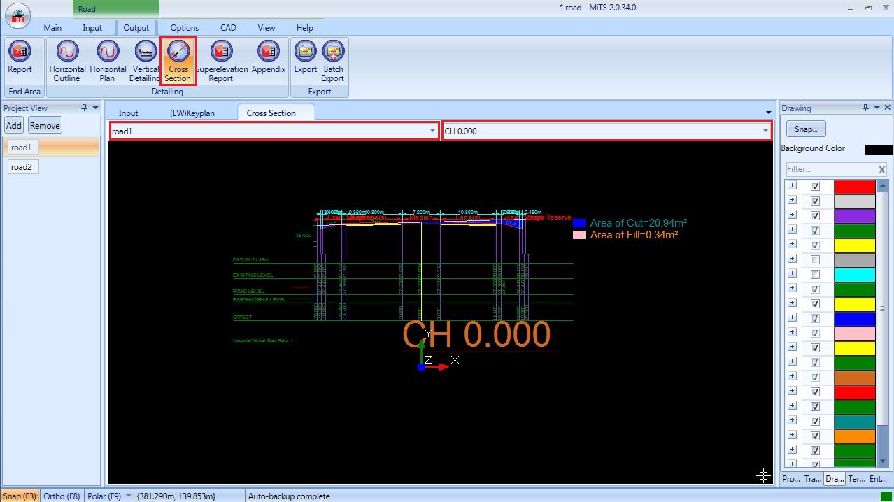
Cross Section Road Output #
The cross section detailing of certain roads and chainages (at a specific interval) can be viewed from the drop down list.
Users may change the interval at Project Parameter settings.
Cross Section Road Output with Title Block #
Users are now allowed to import ‘title block’ into Road Cross Section to be hassle free from rearranging the ‘cross section’ manually to be fit into the title block.
Steps & Procedures
- Go to Options > Project Parameters > CAD Layout > Title Block > click on ‘more menu icons’ to import ‘Title Block’ drawing

Note:
Margin: the margin between the paper and the Title Block
Padding: the title block margin for meta information such as company name, company chop etc
- Select paper type; either A1 or A3
- Go to Road > Output > Cross Section > Title Block

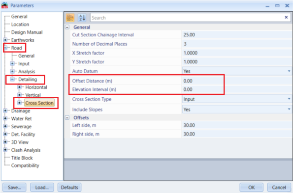
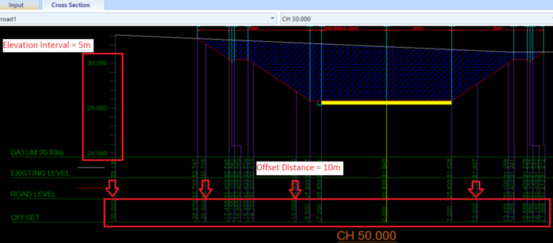
Customize the indication of levels at Cross Section #
Go to Parameters > Road > Detailing > Cross Section > ‘Offset Distance’ and ‘Elevation Interval’
For example, Offset Distance is 10m and Elevation Interval is 5m.
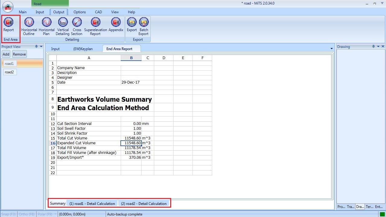
End Area Method Road Output #
Earthworks volume calculation can be viewed by clicking on End Area Report Tab. The detail calculation can be seen at the bottom tab.
Superelevation Report #
Click the Superelevation Report tab to view Horizontal Detailing, Vertical Detailing, Superelevation Excel Report and Appendix.


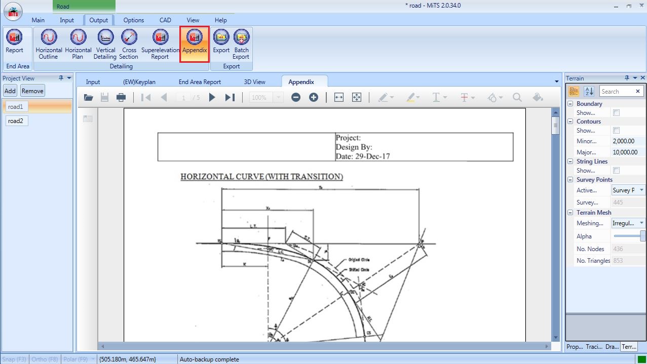
Appendix #
All formulae used to calculate horizontal curve and vertical curve will be listed in the appendix for reference.
Generate Platforms #
Click Generate Platforms to generate the road platforms and the platforms will be synced in the Earthwork module. Click Clear Platforms to remove the road platform from being generated in the Earthwork module.

Generate Drains #
Drains generation can only be done if drain reserve is created (refer to section 5.7). Click on Generate Drains to generate the entity. Nodes and Drain Pipes will be automatically created and synced in the Drainage module. All of the inputs can be adjusted in the Drainage module.

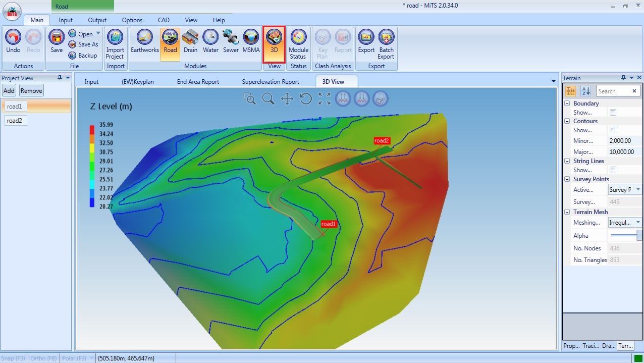
3D View #
The 3D view of the road(s) modelling can be viewed by going to the main page and click on the “3D View” tab.
The view can be altered by clicking the buttons on the upper right side.

I’m the Benevolent Dictator for Life for MiTS Software cum Editor of this website. Read more here.
You can also contact me at soonhui@mes100.com


