Creating Line and Curve #
To design a road, users firstly need to Add a road under Project View. Click Add to add road.
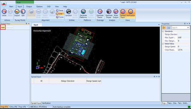
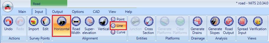
Select Horizontal Alignment and Line icon to input the road string on the drawing. With the Tracing and Snapping feature, the road string can be easily inputted on the drawing.
Click once on the MES-Road screen to activate the snapping, the mouse cursor will turn into precision select, + pointer.
Then, input the road string (centreline). A curve will be generated for every 3 consecutive points drawn (at the intersection of 2 constructed lines). Users can right-mouse click to cancel the input mode or press ESC button to cancel all.
Users may rename the road in Project View Tab by clicking once on the road name.

Horizontal Point #
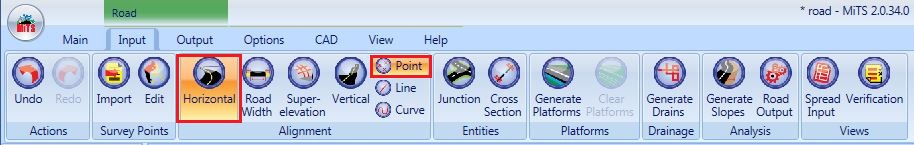
Users have to select the “ Horizontal Alignment” and “ Point” icon before editing the point properties. The IP points in the drawing can be dragged to any desired location. If an intermediate IP point is deleted, the road will join the IP points before and after the deleted point.
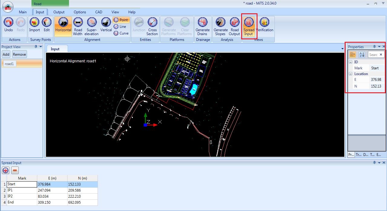
Point properties can be inputted in Spread Input (IP Points Properties Table) or properties bar.
Click the “ Spread Input” button for spread input or simply select an IP point and input the IP point properties in the properties tab (on the right hand side).
Spread Input #
The coordinates of the IP points can be edited in spread input. E (East) indicates the x-coordinate while N (North) is the y-coordinate. The mark of the IP Points can be changed too.
If a user dragged an IP point to a new location, the coordinates of the new location will be auto updated in the spread input and properties tab.

Horizontal Line #
Select “ Horizontal Alignment” and “ Line” before inputting the line properties. Similar to Points Properties input, the Line properties can be inputted in Spread Input or properties bar by selecting the particular line.

Spread Input #
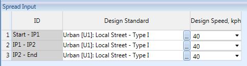
Design Standard #
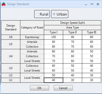
Click three dots button at the Design Standard column to show the Design Standards Table for selection of design speed.
Select Rural or Urban standards. Then, select the appropriate design speed based on type of area/terrain and the road category with respect to the rural or urban standards.
Horizontal Curve #
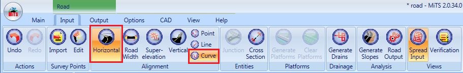
Select “ Horizontal Alignment” and “ Curve” before inputting the curve properties. The Curve properties can be input in Spread Input or properties bar by selecting the particular curve to be inputted.
Spread Input #
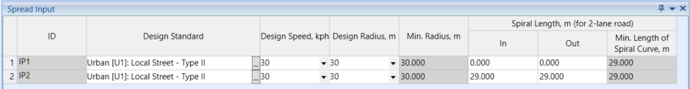
Similar to Design Standards in Line, click the button for the Design Standards Table. Then, select the appropriate design speed based on the urban or rural standards. The design speed can be reduced if needed. The design radius of the curve can be set but it must be greater than the minimum design radius shown.
The minimum length of spiral curve for a 2-lanes road will be auto calculated by the program based on the design speed and curve radius according to REAM guidelines. For roads with more than 2-lanes, the exact length of the spiral will only be able to show the result after analyzing.
(i) Runoff Length
The spiral length, also known as the runoff length, can be edited by the user under the Properties.

The Runoff Length Calculation Method can be opted by the user under the Properties as shown below.

Note:
- Fixed method : defined value under in/out spiral length multiply the adjustment factor
- Max. Relative Gradient method: runoff is based on value calculated by using transition length formula
(ii) Runout Length
By default, the Runout length calculation method in the program is Auto Calculate in which the calculation is done based on the transition length formula. To include values from Table 4.8 (ATJ 8-86 Pindaan 2015) as the runout length, the parameter need to be changed to User Defined under Properties as shown below;

Users can also edit the value of the In/Out Runoff Length under the Spread Input.

How to input Small Road Design Radius #
Some projects might not need to follow to JKR guidelines. Therefore, the user may alter the design radius for road design.
There are two ways, user can change the radius
- Change the properties at RHS tab.
- Firstly, user needs to select the road that needs to be changed.
- Then, user may click on the drop down button at the Min. Radius and choose “None”.
- However, the user must make sure that it is within the horizontal alignment and curve line.
- User can change the design radius at the Spread Input tab. Just make sure that the Spread Input button is on

- Change at the Project Parameters
- User may go to Option > Project Parameters > Road > Design > Min. Radius Standard
- After that, switch “JKR” to “None”
- Same as previously, user may change the Design Radius at the Spread Input tab

Vertical Alignment Point (VIP) #
With the use of the VIP feature, users may see where the road is vertically aligned in the horizontal view. The user can add, change, or remove the vertical alignment point with this feature
To activate the VIP function, user may go to Input > Horizontal > VIP

Spread Input #
User may refer to the spread input tab to know the properties of the vertical alignment point. The purple colour dots is the location of the vertical alignment point.

How to add Vertical Alignment Point in Horizontal View #
In addition to being able to change existing vertical points, users can also add new vertical points. The next digital box will appear when you click on any desired location on the road

User can alter the chainage and insert the elevation before clicking ‘OK’

I’m the Benevolent Dictator for Life for MiTS Software cum Editor of this website. Read more here.
You can also contact me at soonhui@mes100.com


