(This is already outdated; please refer to our user guide for the latest information)
CLASH ANALYSIS
Purpose : To check the clash between drainage, water reticulation and sewerage
1.0 Clash Analysis
Make sure analysis of at least two of the networks has passed (drainage, water reticulation and sewerage)

Image 1 Analysis for Drainage, Sewerage and Water Reticulation have passed
Then, click on Clash Analysis tab as in image 2.

Image 2 Clash Analysis Tab
Set material thickness, minimum vertical clearance and minimum horizontal clearance.

Image 3 Material Thickness and Clearance are set
Material thickness indicates the thickness of the material used in the pipe while minimum clearance is the vertical or horizontal space between two entities.
2.0 Vertical Clash Analysis
Project reference: here
Example of calculation of each remark can be referred as in the spreadsheet. Click here.
Remarks:
OK : Vertical clearance > minimum value set
Insufficient : 0 ≤ Vertical clearance < min Vertical clearance
Clash : Vertical clearance < 0
Based on assumption, drainage is above water pipe, and water pipe is above sewerage pipe.
Formula for Vertical Clearance:
- Sewer and Water = Water IL – (Sewer IL + Sewer Pipe Diameter)
- Drain and Water = Drain IL – (Water IL + Water Pipe Diameter)
- Sewer and Drain = Drain IL – (Sewer IL + Sewer Pipe Diameter)
2.1 Key Plan
Exclamation mark on key plan indicates the clash that occurs between the entities. Yellow mark means insufficient, while red mark means clash.

Image 4 The warning signs are shown in keyplan
Directed to 3D View:
Right click on the sign >> Click on Show in 3D View (Image 5)

Image 5 Directed to 3D View
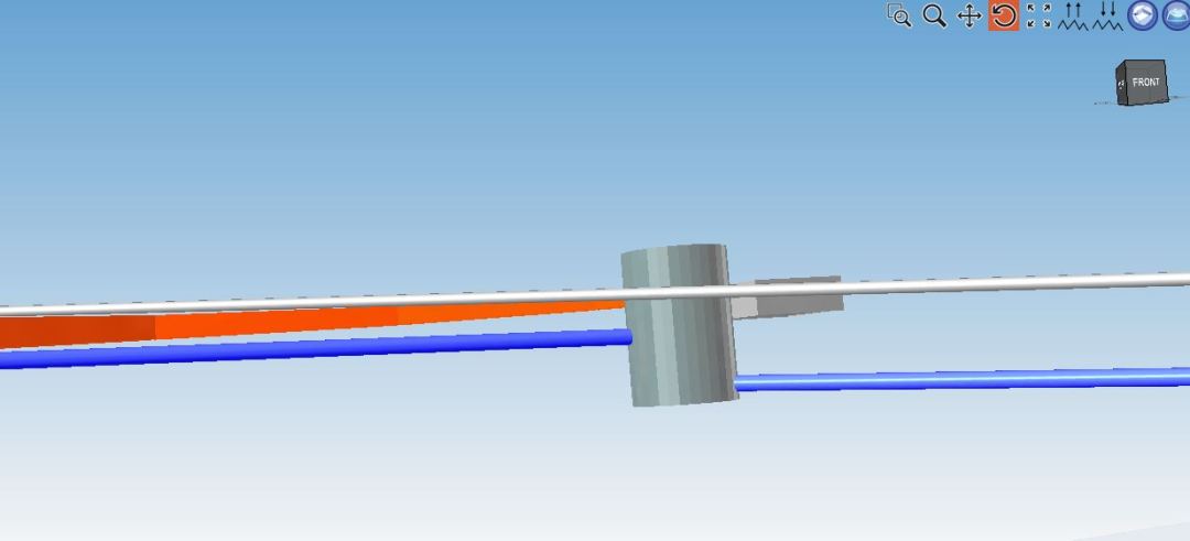
Image 6 3D View
Image 6 shows the 3D View of that particular clash point as shown in Image 5.
2.2 Report
Go to:
Vertical >> Report

Reports over the three entities are shown. Each of the remarks is explained in 2.0.
2.2.1 OK Remark
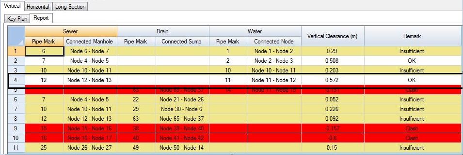
Image 7 OK Remark for Sewer Pipe Mark 12 and Water Pipe Mark 11
OK remark means that the vertical clearance is more than the minimum clearance. In this case, sewer 12 and water pipe 11 are not clashed and the clearance between two entities is sufficient which is more than the required minimum clearance distance.
The calculation can be referred as per attached in the spreadsheet at section 2.0.
2.2.2 Insufficient Remark
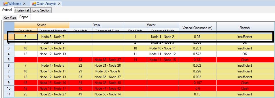
As can be seen as image 8, Sewer Pipe Mark 6 and Water Pipe Mark 1 is in “Insufficient” remark.

Image 8 Sewer pipe 6 and Water pipe 1 is insufficient.
Insufficient means that the vertical clearance between the entity is less than the required minimum vertical clearance. Image 8 explains that the vertical clearance between sewer pipe mark 6 and water pipe mark 1 is less than the requirement. Therefore, it is insufficient.
The detail of the calculation can be referred to the spreadsheet attached above at section 2.0.
2.2.3 Clash Remark

Image 9 Sewer Pipe Mark 19 clashes with Drain Pipe Mark 38
Clash remark means that the entities are intersected or clashed. As can be seen in Image 9, sewer pipe mark 15 and drain pipe mark 38 are clashed.
Example of the calculation can be referred as per attached in the spreadsheet in section 2.0.
3.0 Horizontal Clash Analysis
Project reference: here
Horizontal >> Report

Remarks:
“-” : Intersected point at key plan but never clash
-ve : Clashed with Sump/Manhole
+ve : No clash at key plan but clashed considering the thickness of Sump/Manhole
3.1 “-” Remark
“-” remark means that the entities seems to be clashed by viewing at key plan but never clash and can be proven by viewing them vertically.
Horizontal >> Report

Horizontal >> Key Plan

Image 10 Water pipe 1 and sump 1 are clashed on Key Plan.
Go to 3D View to view a clearer image.

3D View with Contour/PL View

Image 11 3D View shows that water pipe does not clash with the sump.
As shown above in image 11, water pipe seems to be clashed with drainage sump at key plan but not vertically.
3.2 -ve Remark
“-ve” value means the entities are clashed.
Horizontal >> Report
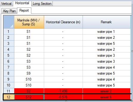
Image 12 Negative value of horizontal clearance is red highlighted
Double click on row 12 to be directly directed to the clash point in the keyplan.

Image 13 Clash point is shown in the keyplan after double clicking in the report
Right click on the clash to view the 3D View.

Image 14 Horizontal clash can be seen between the sump and the sewer line
3.3 + Remark
+ remark indicates the clashings happen within thickness. The measurement is calculated based on the inner profile of the involving entities.
Calculation:
The horizontal clearance is calculated perpendicularly between the entities. The thickness of the pipes is excluded in horizontal clearance measurement. This can be explained based on the image below.

Image 15 Horizontal clearance of 576.31 mm between sump 12 and sewer 6
Image 15 shows the measurement of horizontal clearance between the sump 12 and sewer 6 which is 576.31 mm, which explains the value of 0.571 m in the Clash Analysis report.
4.0 Clash Point Solution
4.1 Change the properties (invert level, slope, location and etc.) of drainage, water reticulation or sewerage.
Example:
Based on section 2.2.2 clash
Go to sewerage tab

Change the invert level of node 6 from 28.300 m to 28.000 m and analyze.
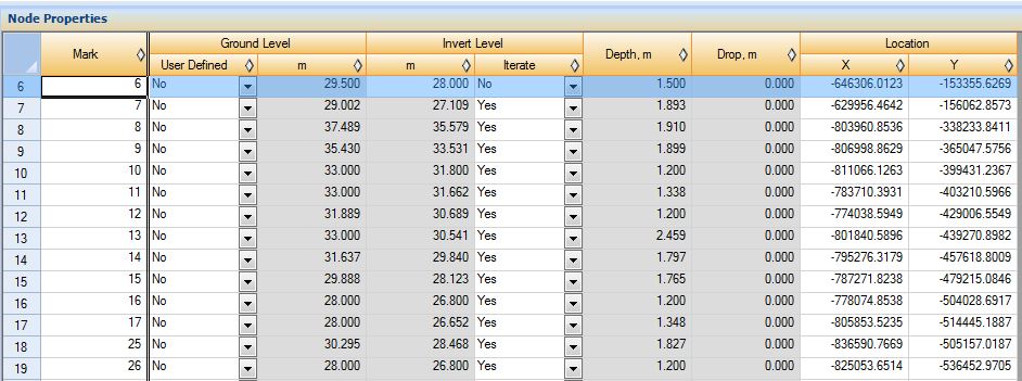
After analyzing, go to Clash Analysis tab.
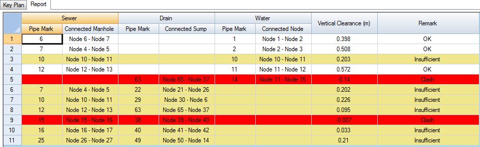
Image 16 Distance between Sewer pipe mark 6 and Water pipe mark 1 is no longer insufficient
Image 16 shows that vertical clearance between sewer pipe mark 6 and water pipe mark 1 remark is “OK” explaining that the two entities distance is more than the minimum vertical clearance.
4.2 Move the location of sump or manhole
Based on section 3.2 clash
Example:

Sump 12 is horizontally clashed with sewer 6
Go to drainage tab
Move a bit node 12 location about 0.5 m away from the original location and analyze.
Go to Clash Analysis tab.

Image 17 Sump 12 and sewer 6 horizontal clash has been removed
Image 17 shows that sump 12 and sewer 6 is no longer appears in the report indicating that those two entities is no longer horizontally clashed.

I’m the Benevolent Dictator for Life for MiTS Software cum Editor of this website. Read more here.
You can also contact me at soonhui@mes100.com